Undamped Critical Speeds for Simple Rotors - Plus Cheat Sheet
In rotordynamics, a critical speed can be most simply described as a rotational speed that coincides with a natural frequency of the rotor, leading directly to mechanical resonance. The critical speed is of utmost importance in the design and operation of turbomachinery for this reason.
 Before delving deeper into the meaning and calculation of critical speeds, it is worth discussing where the term itself came from. The first published analysis in the rotordynamics of turbomachinery was by Rankine in 1869. In that paper, Rankine utilized the spring-mass model in a rotating coordinate system, leading to an incorrect application of Newton’s second law, and thus drawing the erroneous conclusion that every rotor had a lowest natural frequency, which if crossed, would lead to immediate resonance-induced failure, hence the word “critical”. Though ultimately shown to be incorrect, Rankine’s work is still of theoretical and scientific value, because he related the spring-mass model to rotor vibration and rotational motion, which is still used to this day to analyze rotor behavior.
This blog is part of our Rotating Machinery Diagnostics Series, and will cover:
Since a critical speed is a resonance frequency, a logical place to begin the mathematical discussion is with the natural frequency in radians per second (rad/s):

In terms of Hz (s-1) we have, from (1):

To obtain the frequency in terms of revolutions per minute (rpm), we multiply the result in (2) by a factor of 60:

The results in (3) form the basis of the critical speed calculations we will utilize in this discussion. Unless otherwise noted, critical speed will be taken to mean undamped critical speed for the purposes of this discussion. A more general form of the critical speed is the one stated in terms of the maximum static deflection of a simple beam under an applied load:

Where g is the local acceleration due to gravity and xst is the maximum static deflection, which is easily obtained from tables for most cases of applied interest. Critical speeds are often cataloged graphically in what is called at critical speed map. This graphical catalogue serves two main purposes: to illustrate the relationship between support (i.e., bearing) stiffness and the critical speeds/resonant frequencies, and to tell us which speeds to avoid during operation. A representative example of such a map is given below for a generic rotating machine.

Figure 1: Undamped lateral critical speed map.
The quantity “cpm” is taken to mean “cycles per minute” and is dimensionally equivalent to rpm. The first, second, and third critical speeds for this machine are denoted by cpm 1, cpm 2, and cpm 3 respectively. Note that as the bearing/support stiffness increases, the second and third critical speeds converge, while the gap between the first and second critical speeds increases significantly once the bearing/support stiffness exceeds 105 lb/in. This gap is often quantified as the separation margin (SM) and is important in specifying an operational cushion for rotating machinery, especially in those cases where the machine operating speed is beyond the first critical speed (such is the case much of the time, with one notable exception being cryogenic turboexpanders, which typically operate at very high speeds and below their first/lowest critical speed).

Lateral & Torsional Critical Speeds (Vibration)
Critical speeds can be broadly categorized as lateral or torsional, depending on the type of vibration under consideration. The term “lateral vibration” in rotordynamics refers to the radial plane orbital motion of the rotor about its spin axis. This is the best understood form of rotor vibration, and the one most easily monitored, controlled, and designed against. Correspondingly, the term “torsional vibration” refers to the oscillatory twisting of a rotor about its centerline and superimposed upon its angular spin velocity. It bears mentioning that these modes of vibration are rarely coupled in practice (that is, mutually interact in a physically meaningful way), with one notable exception being gear-coupled systems consisting of more than one rotor (ex. integrally geared compressors). A more extended discussion of the lateral/torsional dichotomy can be found in the accompanying cheat sheet and will be illustrated below with algebraic and numerical examples using formulas from tables in the cheat sheet.
Calculating Undamped Critical Speeds
Rotors for engineered turbomachinery such as gas turbines, multi-stage cryogenic pumps, centrifuges, and screw compressors are highly complex mechanical systems. As such, direct calculation of their critical speeds using classical methods is, for most practical purposes, functionally impossible. That said, there is a large class of turbomachines, such as centrifugal fans and single-stage/between-bearing pumps that are amenable to simple calculation methods, at least to a first approximation. The value added by doing so is twofold: first, it allows us to obtain an accurate numerical estimate of a key machine parameter directly, provided that the required information is available. Second, and perhaps more importantly, such methods allow us to establish physically realistic ranges of values for a significant number of performance-related parameters while referring said parameters back to the rotor speed. This is illustrated in the examples below.
Example 1: Direct Calculation of Lowest Critical Speed for Centrifugal Fan (Weightless Shaft)
A center-hung fan rotor is shown below in Figure 2.
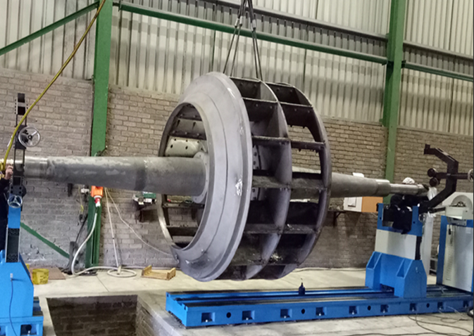
Figure 2: Center-hung fan rotor
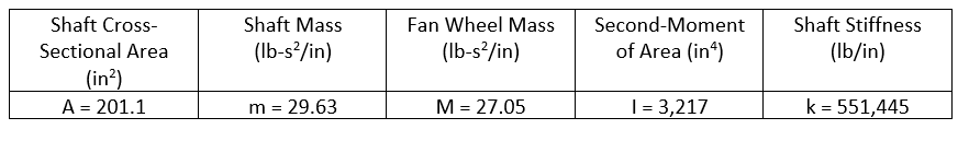
The Shaft diameter (D) is 16 in, and the span between the bearings (L) is 201 in, the fan wheel weighs 10, 447 lbs, and is made out of carbon steel (ρ = 0.283 lb/in3). The shaft, also made out of carbon steel, has an elastic modulus (E) of 29.0x10⁶ psi (lb.in2). The numerical values are tabulated below:
We make a direct application of the first formula from the first table in the attached cheat sheet to obtain:
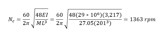
The first (lowest) lateral critical speed, without the weight of the shaft is 1363 rpm.
Example 2: Direct Calculation of Lowest Critical Speed for Centrifugal Fan (Shaft Weight Included)
Here we incorporate the weight of the shaft in the calculation of the first critical speed for the center-hung fan rotor of Example 1. A common and expedient way of doing so is to divide the shaft mass by two and add it directly to the mass of the disc, in this case the fan wheel:
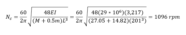
By neglecting the shaft mass in Example 1, we overestimated the first critical speed by 267 rpm – a difference of 22%. The two examples above illustrate cases where a direct calculation is both needed and feasible, such as when a shaft has just been repaired or an impeller/blade has been replaced. In such circumstances, we would have the advantage of the rotor being in a controlled environment (the shop) and being able to measure geometric dimensions, as well as obtain material data from the OEM. The two examples below will illustrate cases where the critical speeds are not known, and general relations for the rotor speed need to be determined in terms of physical and performance-related parameters. This is often done during the preliminary design phase, and assists designers with, among other things, the placement of critical speeds and the identification of no-run zones.
Example 3: Determination of Liquid Rocket Engine Turbo-Pump Operating Speed
Turbo-pumps for liquid-propellant rocket engines are highly complex turbomachines, and a complete description of their function, design, and operation is beyond the scope of this discussion. Our focus in this example will be on the establishment of parametric relationships for turbo-pump operating speeds to assist in the determination and placement of critical speeds.
In a liquid-propellant rocket engine, the turbo-pumps play the crucial role of increasing the pressures of the liquid propellants above the values of those in the storage tanks, to enable the injection of said propellants at high pressures into the combustion chamber. The pumps used for this purpose can be centrifugal flow, axial flow, or mixed-flow. These designations breakdown based on how the pump transports the fluid, with mixed-flow being a compromise between centrifugal and axial flow types. Figures (3) and (4) below respectively show centrifugal and axial flow turbo-pumps.
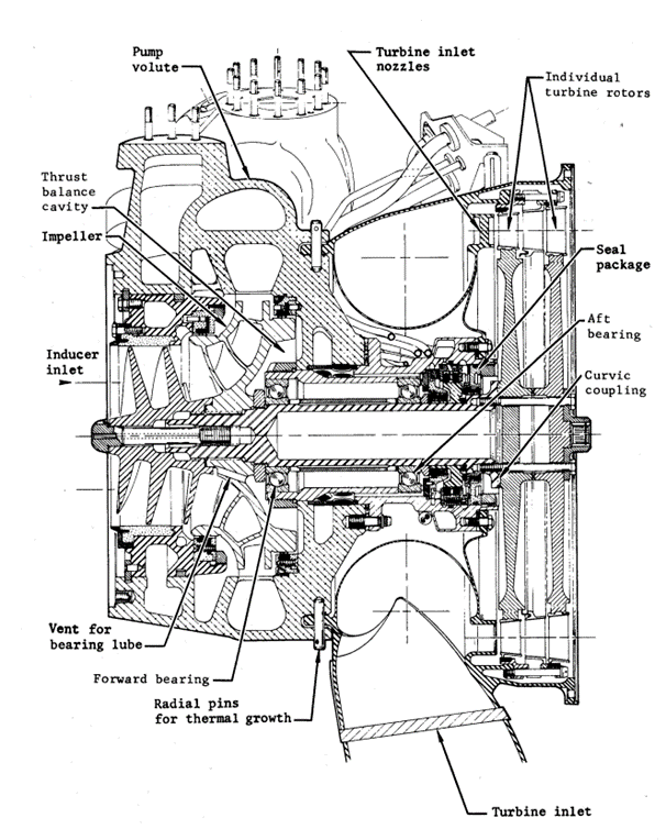
Figure 3: Centrifugal flow turbo-pump assembly (NASA)
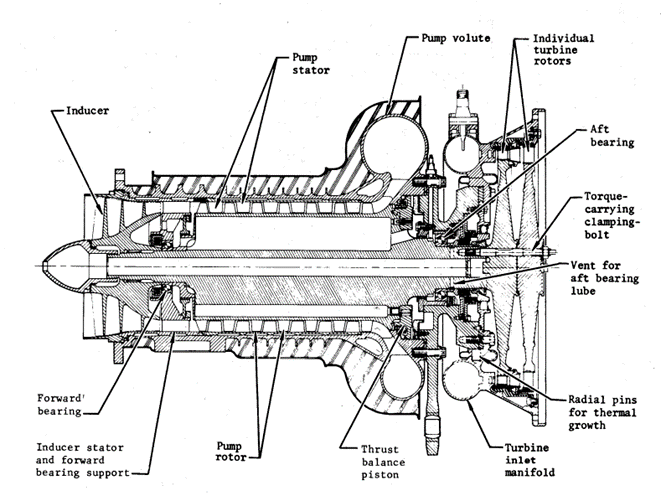
Figure 4: Axial flow turbopump assembly (NASA)
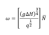
We begin with the pump specific speed, a non-dimensional parameter (really a parameter grouping):
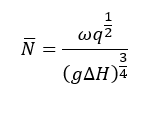
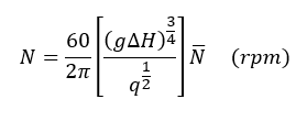
Where ω is the shaft angular velocity (rad/s), ΔH is the head rise at the pump best efficiency point, or BEP (m), q is the volumetric flow rate (m3/s), and g is the local acceleration due to gravity (g = 9.81 m/s2). Current flight-proven values for pump specific speeds are between 0.16 to 0.77 for centrifugal-flow pumps and 1.17 to 4.02 for axial flow pumps. After a little algebra, we obtain the operating speed as:
Applying Equation (3) for the operating speed, we obtain:
From here, we can work backward to determine where the critical speeds should be placed in relation to the range of operating speeds. Importantly, this relation also allows us to determine operational speeds/frequencies for vibration-based condition monitoring and diagnostics. Vibration is the single most important parameter in assessing the health and performance of turbomachinery.
Another important speed/frequency we can analyze using the above methods is the suction specific speed, which is used as an index for cavitation performance. This is important in any pump, but is of heightened importance in pumps used in liquid propellant rocket engines due to the fact that the working fluid is at cryogenic temperatures:
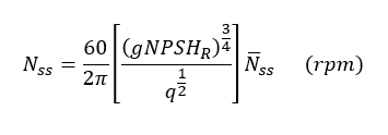
We obtained the above relation by replacing the head rise at the BEP with the net positive suction head required (NPSHR). The NPSHR is used as an index for the amount of head required at suction (intake) to prevent cavitation and is of considerable importance in centrifugal-flow pumps. This speed/frequency is important in vibration-based diagnostics because heightened vibration at/near this frequency could be an indication of cavitation, which can ultimately lead to mechanical failure. Rocket turbo-pumps typically operate up to a suction specific speed of about 18. Our final example will use the relations from Table 3 for torsional critical speeds in the attached cheat sheet to show (conceptually) how we can work backward from the critical speed to help size an integrated shaft coupling for a marine propulsion application.
Example 4: Sizing of An Integrated Shaft Coupling Based Upon Torsional Critical Speed
Marine propulsion systems are often characterized by single-dive line machine trains that are connected via couplings. A simplified schematic of such a system is shown below in Figure 5.
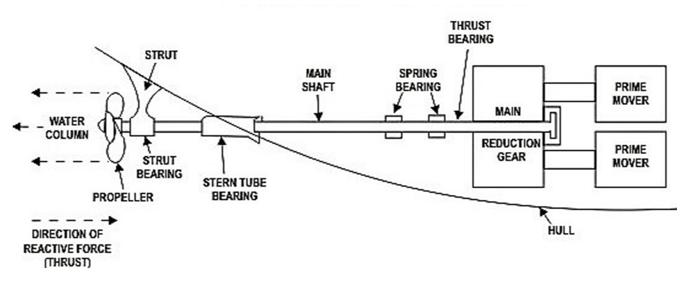
Figure 5: Marine propulsion system schematic
It is easy to see from the schematic why torsional vibration would be of concern. The main shaft is long and flexible. It is also connected via couplings to an n-reduction gearbox, which is in turn connected to a prime mover. Often, the ship will have to adjust speed, resulting in varying/transient torques being applied to throughout the machine train (shafts, gears, couplings, etc.). With all of this in mind, we will now apply the concept of torsional critical speed to establish a parametric relation that can be used to determine the appropriate size (length) of an integrated shaft coupling. An example of the use of this type of coupling is to connect an electric motor to a propeller drive shaft.
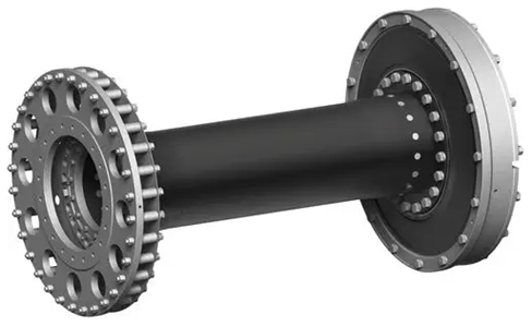
Figure 6: Integrated shaft coupling
The coupling in Figure 6 corresponds to the first case in Table 3 (see cheat sheet):
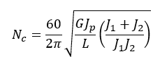
Because this is a sizing problem, the idea is to isolate the coupling length L, and express it in terms of all of the other parameters. After a bit of algebraic wrangling, we obtain:
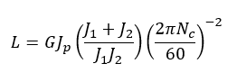
If the shear modulus and the respective polar/mass moments of inertia are known or can otherwise be found (the simplest case) then we can say the length of the coupling varies inversely with the square of the critical speed. This might lead us to ask if there is some optimum value of the length L within a prescribed range of critical speeds that would best solve the problem. The answer is yes, and said value is found through a process called mathematical optimization based upon the methods of differential calculus. As we can see, determining the above relation was the easy part; the hard engineering work begins after we had found what we were looking for.
Concluding Remarks
It is hoped that the above series of examples and the attached cheat sheet will be of both practical and educational use to practicing engineers, technicians, students, and anyone interested in rotordynamics. As previously stated, the tables and associated examples aim to provide and illustrate a basis for simple preliminary inquiries as they relate to the undamped critical speeds of simple rotor systems.
Rotating Machinery Vibration Series
This post is part of the Rotating Machinery Vibration Series. Feel free to check out my other related posts;
- Overview of Synchronous Vibration - Plus Cheat Sheet
- Gear Noise & Vibration: Why it is Important
- Machinery Condition Monitoring: A High-Level Overview
- Basic Elements of Machinery Diagnostics: An Overview