Machine Condition Monitoring: A High-Level Overview
The purpose of capturing machine data is to allow the owner/operator/end-user of the machine to make timely determinations as to whether the machine is in “good” or “bad” condition. In practice, this is almost always significantly more complicated than it sounds
Machinery condition monitoring can be defined as follows:
The collection of procedures and technologies applied for the purpose of evaluating the functional performance of a machine in accordance with operational specifications using measured data.
To accomplish this, instrumentation is deployed to measure various parameters that are taken to be indicators of the mechanical condition of the machine in question. Such parameters can include vibration, machine speed, bearing/lube-oil temperature, volumetric flow rate, pressure, etc. This blog is a part of the Rotating Machinery Diagnostics Series, and will cover:
- Characterizing & Implementing Condition Monitoring Systems
- Classification of Machinery
- Determining Vibration Thresholds
- Concluding Remarks
From this point on, we will use “condition monitoring” synonymously with “machinery condition monitoring”, with a focus on industrial rotating machinery (centrifugal pumps/compressors, gas turbines, etc.), though many if not most of the programmatic characteristics we will discuss carry over readily to any predictive or preventive maintenance program with which condition monitoring would be used in conjunction.
Predictive maintenance describes an approach to machinery maintenance that utilizes machinery performance data to identify and interdict mechanical problems before they reach the point of inhibiting the safe and effective operation of the machine. Preventive maintenance describes an approach to machinery maintenance where mechanical components are replaced on a periodic basis in accordance with a set schedule irrespective of the condition of the machine. The reader may have already ascertained that the former approach is more economical than the latter, especially when one considers lead/turn-around times for turbomachinery repairs (ex. it is not uncommon for a set of fluid-film bearings to take 12 weeks to procure and install, and they can easily cost tens of thousands of dollars).
While the economic argument alone may be more than enough to justify implementing a condition monitoring program, it is worth taking a moment to enumerate the merits of implementing such a program:
- Monitoring reduces the occurrence of unexpected/unplanned outages
- Monitoring minimizes production loss by helping to ensure maximum up-time
- Monitoring reduces both the frequency and necessity of intervention
- Monitoring minimizes maintenance costs
The importance of all the aforementioned parameters notwithstanding, primacy will be given to the use of vibration measurements in the monitoring of machinery condition. The reason for this straightforward:
Of all the aforementioned parameters, it is vibration that is the most useful in diagnosing the broadest range of mechanical faults.
While condition monitoring and diagnostics are, for good reason, inherently bound-up with one another, they are not, strictly speaking, the same thing. While machinery condition monitoring seeks to absorb, program, develop, and deploy procedures & technologies, machinery diagnostics has as its primary focus the actual analysis of the machinery performance data. Machinery diagnostics is an integral and vital part of any condition monitoring program. Given the nuance, depth, and highly technical nature of machinery diagnostics, a detailed discussion of diagnostics techniques will be reserved for another article.
Characterizing & Implementing Condition Monitoring Systems
Condition monitoring systems can be broadly divided into two classes:
- Periodic
- Permanent
Periodic
In the case of periodic (off-line) condition monitoring, machinery performance data is captured via direct measurement at prescribed intervals at the physical location where the machine is in operation. By definition, the devices/instrumentation used to capture and later analyze the machinery performance data are not permanently fixed upon the machine. This approach to condition monitoring is often employed in conjunction with permanent (on-line) condition monitoring systems to enhance overall protection of critical machines (more on this later). Periodic monitoring is especially useful when measurements have to be taken at many locations on/around the machine, and when detailed (i.e., location-specific) data is required for advanced diagnostics and/or early fault detection.
Permanent
A permanent monitoring system is the direct inverse of a periodic monitoring system. In the case of permanent monitoring, machinery performance data is measured continuously at specific points on a machine during operation and is compared in real-time to pre-established thresholds for the monitored parameters. Unlike periodic monitoring, the instrumentation used to capture machinery performance data is permanently fixed to the machine. This approach is often utilized in situations where no personnel are available (or trained) to perform direct measurements, a fault or breach of threshold requires immediate shutdown, or the physical environment is non-permissive and/or physically dangerous (ex. nuclear reactor).
The functional aspects of condition monitoring, whether it be periodic or permanent, place a premium on the following two factors:
- Criticality of the machine
- Establishment of alert/alarm thresholds
Prior to discussing classification of machinery in accordance with criticality and the establishing of alert/alarm thresholds based on monitored parameters, it is instructive to take stock of the basic requirements of a condition monitoring program. When implementing a condition monitoring program, the steps enumerated below should be followed:
- Determine the type of condition monitoring system (periodic/permanent/combination).
- Determine which machines are to be monitored.
- Document machine characteristics (parameters) that are most important in relation to machine performance (natural frequencies/critical speeds, operating speeds, bearing clearances, etc.).
- Select the most appropriate vibration parameter (displacement, velocity, or acceleration) to measure. This choice will be situationally driven and will depend heavily on factors such as machine type/operating speed, dynamic range of the transducer, etc.
- Select a transducer/transducers based on the parameter/parameters selected in Step (4) above.
- Determine the locations where measurements are to be taken.
- Determine the time interval at which measurements will be taken (most applicable to periodic monitoring).
- Determine the order or sequence in which data will be acquired. This can be a function of machine location/criticality, plant layout, cost, and any number of other factors (most applicable to periodic monitoring).
- Select the appropriate data acquisition & analysis system based on Steps (1) through (8) above.
- Select and implement a secure data storage system. Data is currency, and it should be treated as such.
Classification of Machinery
Classifying machinery on the basis of criticality may be the single most important aspect of any condition monitoring program. Broadly speaking, a machine is considered “critical” if malfunction or failure leads directly to production loss and/or the failure of other systems at the point of use, be it a power generation plant, chemical process facility, water treatment plant, or any other industrial setting where the operation of the machine plays a vital role. This seems intuitively clear, but how is a hierarchy of machine criticality established?
While there is no end-all/be-all classification system, we do have some solid working guidelines based upon hard-won experience. These guidelines are tabulated below in descending numerical order with (1) being regarded as “critical” and (4) being regarded as “non-critical”.
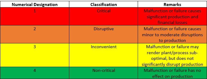
Table 1: Machinery classification based upon level of criticality
The level and extent of machine criticality are the primary factors to consider when devising and implementing a condition monitoring system.
Determining Vibration Thresholds
The determination of appropriate vibration thresholds is of paramount importance. More often than not, plants where large quantities of rotating machinery are present use overall vibration trends (amplitude against time) as the primary indicator of machine health. If the overall vibration breaches a pre-specified alert/alarm setpoint, then a series of investigative and/or corrective actions are (in theory) taken that are specific to the machine, plant, and process. Due to these prespecified alert/alarm setpoints often being the primary means of protecting the machine, it is essential that they be set low enough to give a reliable indication of excess vibration, but not so low that they lead to the occurrence of so-called “nuisance alarms”. The author has had first-hand experience where repeated alerts/alarms regarded as nuisances went ignored by plant personnel and culminated in a catastrophic machine failure.
The tables below provide reliable technical guidelines with regards to the setting of vibration thresholds for condition monitoring. These values are not sacrosanct. It is not uncommon for machines in the corresponding categories to operate effectively well-above these levels for months or even years on-end, and it is also not uncommon for said machines to malfunction or fail well-below the same levels. When setting alert/alarm thresholds, one should always defer to the original equipment manufacturer (OEM). If the OEM vibration threshold data isn’t available, set the alert level to the lower bound of the satisfactory level (B) and the alarm level to the lower bound of the unsatisfactory level (C) in accordance with the table corresponding to ISO 10816. While this may seem overly conservative, it should suffice to protect the machine temporarily until the next planned outage, or at least until more detailed measurements can be taken to diagnose possible causes. Note: overall vibration levels on a healthy machine should not exceed bearing clearances during on-design operation, and alert/alarm thresholds should be adjusted to reflect this. A usable working guideline is to set the vibration alarm level no higher than 70% of the available bearing clearance. Refer to the Synchronous Vibration Cheat Sheet for units and relations between displacement, velocity, and acceleration for rotating machinery vibration.
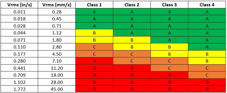
Table 2: Vibration severity in terms of RMS velocity (ISO 10816-1)
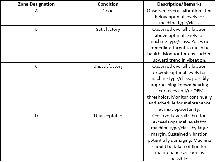
Table 3: Relation between zonal designations and machine condition per ISO 10816 (Table 2)
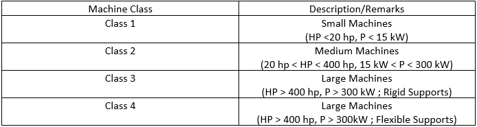
Table 4: Machine classifications based on power rating per ISO 10816 (Table 2)
The table below can also be used as a guide to setting machine thresholds. Here, thresholds are stated in relation to machine operating condition in terms of RMS velocity. As was the case with Table 2, these values are not sacrosanct, and service or “fudge” factors obtained from experimental data may be necessary in order to apply them. These threshold values are not applicable to faults in bearings and gears.
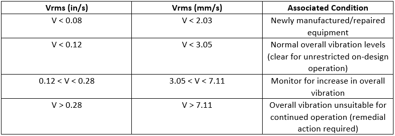
Table 5: Vibration levels associated with machine operating condition
The below charts graphically illustrate the relationship between displacement, velocity, vibration frequency, and severity (Figures 1 and 2). These relations have considerable utility, as there are several common types of rotating machinery (ex. high-speed turbomachinery operating at cryogenic temperatures and enclosed in a thick casing) for which ISO 10816 cannot be applied. In such a case, the vibration measurements must be taken directly off of the rotating shaft, typically using some form of non-contact eddy current sensor, where ISO 7919 is most applicable. Note that 1 mil = 10-3 in = 25.4 µm.
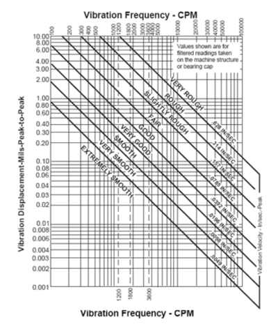
Figure 1: IRD vibration severity chart relating frequency, velocity, and displacement
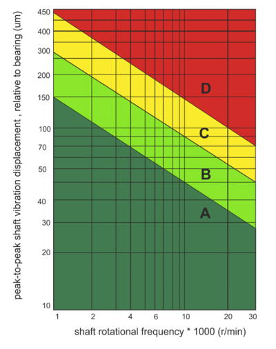
Figure 2: ISO 7919-3 vibration chart relating shaft displacement, shaft rotational frequency, and severity
Concluding Remarks
The establishment and implementation of a vibration-based condition monitoring program for plant machinery requires great care. A properly implemented condition monitoring program will ensure years of trouble-free service for most well-designed industrial turbomachines. An improperly implemented condition monitoring program will engender a false sense of security and may indirectly contribute preventable machinery malfunctions, unplanned outages, costly repairs, and potentially catastrophic machine failures. The intent of this article has been to provide a high-level overview of vibration-based condition monitoring for industrial turbomachinery, as well as general guidelines for the setting of overall vibration thresholds. It will be followed soon by an overview of vibration-based machinery diagnostics. It is always recommended that the services of an experienced vibration professional be sought out when implementing a condition monitoring program.
Rotating Machinery Vibration Series
This post is part of the Rotating Machinery Vibration Series. Feel free to check out my other related posts;
- Overview of Synchronous Vibration - Plus Cheat Sheet
- Gear Noise & Vibration: Why it is Important
- Machinery Condition Monitoring: A High-Level Overview
- Basic Elements of Machinery Diagnostics: An Overview!