Overview of Synchronous Vibration - Plus Cheat Sheet
I've put this blog post and cheat sheet together, as part of a Rotating Machinery Diagnostics Series, to to provide machinery end-users a simple and useable reference to help them understand what is the most common form of vibration observed in industrial turbo machinery and avoid potential faults and malfunctions related to this form of vibration.
In the context of rotating machinery, synchronous vibration is the vibration that occurs at the operating speed of the machine, and is typically denoted as “1X”, where the “X” refers to the multiple of the operating speed, typically reported in revolutions per minute (RPM).
The best known and most common form of synchronous vibration in rotating machinery is unbalance. Unbalance has become so synonymous with synchronous vibration that the two are often taken to be the same thing. In fact, they are not; synchronous vibration can refer to any oscillator (or system of oscillators) subject to a sinusoidal input force at a single frequency:
![]()
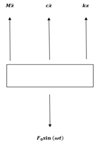
Figure 1: Free body diagram of oscillator with sinusoidal input
It is from the steady-state solution to Equation (1) that the inputs represented in the below tables are derived:
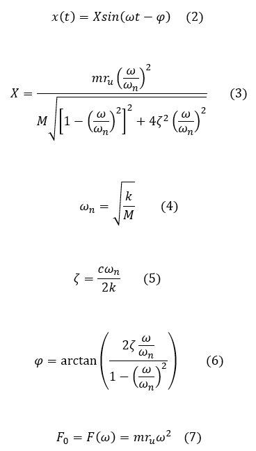
Here, we’ve obtained the steady-state solution for the case of unbalanced rotating mass modeled as an external driving force at the operating speed/frequency of the rotor (ru is the radial distance of the unbalance mass from the center of rotation). The constants/parameters corresponding to the steady-state solution described by Equations (3) through (7) are tabulated below.
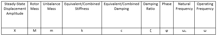
Figure 2: Tabular summary of constants/parameters for the steady-state solution of Equation (1) for rotating unbalance

Why These Tables Are Useful
Precision manufactured turbomachinery is very expensive, often on the order of millions of dollars. Repairs, depending on their extent, can be quite costly in terms of both time and dollars. Malfunctioning machinery, or even machinery that is operating sub-optimally, can disrupt critical operations and pose a potential safety hazard. It is with all of the above in mind that the vibration-based monitoring & diagnostics of rotating machinery has been undertaken as an important engineering and operational function.
For condition monitoring and diagnostics purposes, the reference frequency is the operating speed of the machine (i.e., the synchronous frequency). There are many practical reasons for this, not least of which is because this will be the speed displayed to the equipment operator as well as by the condition monitoring software. Also, many common machine faults (ex. unbalance, shaft bow, misalignment, thermal variability, etc.) occur at the operating speed/frequency. It has been the experience of the author that an easy-to-use tabular reference relating displacement, velocity, acceleration, and frequency is of practical value. The below tables have been compiled from various academic and industry sources and modified for the intended use.
How To Use These Tables (Example)
Let’s say that Pat Operator notices a spike in vibration on one of his boiler feedwater pumps. His data comes to him in the operating room as acceleration trends with a corresponding machine speed readout. After going out to check that the accelerometers are properly seated and functioning properly, he then has to decide whether to escalate the problem to the plant engineer. To do this, he needs to know the severity of the overall vibration in terms of velocity. What is Pat to do? Referring to the third-to-last entry in the second table, he finds his answer:
![]()
From here, Pat Operator can look up the severity levels in the corresponding manufacturer/industry standards and make an informed determination about the next steps to take in the troubleshooting process.
In Conclusion
This is just one of many ways that the formulas for synchronous vibration we’ve compiled and tabulated can be put to immediate and gainful use by rotating machinery engineers, operators, technicians, and plant managers.
If you find this cheat sheet helpful, please feel free to check out and download my other cheat sheet in the following post: Gear Noise & Vibration: Why it is important.
Rotating Machinery Vibration Series
This post is part of the Rotating Machinery Vibration Series. Feel free to check out my other related posts;
- Overview of Synchronous Vibration - Plus Cheat Sheet
- Gear Noise & Vibration: Why it is Important
- Machinery Condition Monitoring: A High-Level Overview
- Basic Elements of Machinery Diagnostics: An Overview - Coming soon!