Thermocouples are sensors that measure temperature. Their applications range from industrial manufacturing and experimental settings to the meat thermometer you use at home. They are often used anywhere it is important to be able to reliably monitor or record temperature data. I've written this blog to give you an understanding of the function, types, selection, and application of thermocouples.
In this post we will explore:
- The physics behind their function, what types of thermocouples there are, and when to use them
- Different measurement junction properties and their applications
- How to select the right thermocouple for your project and where you can buy them
We will conclude with a brief case study of the selection, installation, and use of thermocouples in an engineering laboratory setting.
For those who are looking to get off the ground quickly, here are three basic steps to set up your temperature monitoring system:
What is a thermocouple?
How do they work?
The core of a common thermoelement probe thermocouple consists of two dissimilar metals brought together at a point. When this point is subjected to a change in temperature (ΔT), a thermal gradient is created across the two dissimilar metals within the point. Due to the thermoelectric effect, also known as the Peltier-Seeback effect, electric potential V forms across this thermal gradient. Calibration between this electric potential and known temperatures allows for determination of unknown temperatures at the tip of the thermocouple. A diagram of a standard K-type thermocouple is shown below in Figure 1.
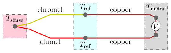
Figure 1: Basic layout of a K-type thermocouple (Source)
This behavior can be described by the following simplified thermoelectric equation derived from the equations that govern the Seeback, Peltier and Thomson effects.
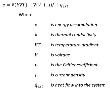
Thermocouple sensor types and their respective properties
Just as there are many varied applications of thermocouples, there exists an array of thermocouple types to meet them. Here we will discuss the two most common types of thermocouples found in industry: probe and surface mount thermocouples. You can find links to in-depth resources at the end of this section.
Probe
Probe thermocouples are used anytime you need to monitor or record the temperature of a fluid or gas inside an enclosed volume, pipe, or pressure vessel. An example of a probe thermocouple is shown below in Figure 2.
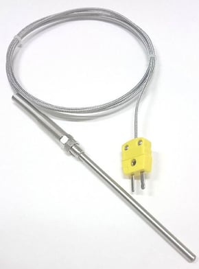 Figure 2: A common probe type thermocouple with extension and connector (Source)
Probe type thermocouple sensors come in a variety of types, the most common of these are thermoelement (dissimilar metal) sensors which are described above, followed by platinum resistance sensors that utilize either a platinum-wire wound or flat film resistor and thermistor type sensors which utilize ceramics (metal oxides). The latter two types - while more expensive - typically have accuracies from 0.1°C to 1.5°C which are significantly more accurate than traditional thermoelement sensors which have an accuracy that ranges anywhere from 0.5°C to 5.0°C. The former thermoelement type thermocouple, while less accurate, is often suitable for most general use applications. A complete table of the similarities and differences is shown below in Table 1.
Table 1: Thermocouple sensor types and their respective properties (Source)

It should be noted that when using probe type sensors in an environment where the sheath and tip of the probe are immersed in the fluid, some error may occur due to heat conduction along the sheath of the thermocouple into or out of the system.
All of these thermocouple types can be found with extension leads of various length with or without connectors, with threaded or unthreaded inserts as well as varying sheath lengths to fit a variety of potential applications.
Different measurement junctions and their uses
In addition to the sensor types discussed above, there are also varying sheath materials used to protect thermoelements in a variety of applications. Here we will briefly touch upon the three junctions that are available as options commercially off the shelf: Exposed, Insulated and Earthed (grounded). Each of these types are shown in the table below in Figure 3.
| Exposed Junction: | Used primarily for measuring the temperature of non-corrosive gas when a faster response time is preferred. | 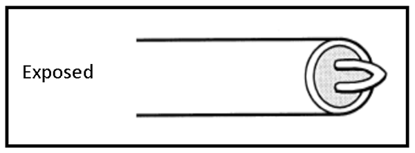 |
| Insulated Junction: | For use in applications where the fluid or gas being measured is corrosive or otherwise harmful to the thermoelement. Due to the insulation, the response time is slower than that of an exposed junction. | 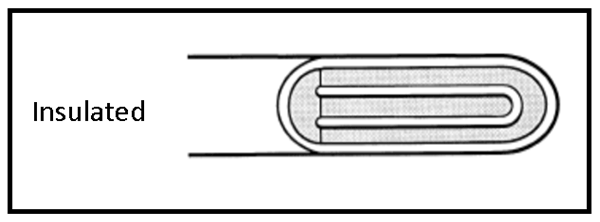
|
| Earthed Junction: | A variation of the insulated junction that is rated for higher pressure applications and has a faster response time. This type is also good for applications that involve corrosive environments. | 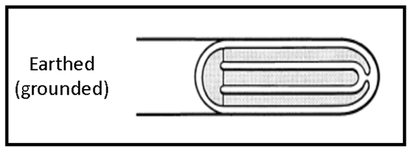
|
Figure 3: Three types of measurement junctions (Source)
Surface Mount
Surface mount thermocouples are similar to conventional thermocouples, however they are different in that instead of the sensor being mounted at the tip of a sheath, the sensor is mounted flush to a flat material which can be fastened to a surface. The flat mounting is to address errors that can be introduced if the entire sensor is not in contact with the surface to be measured. For this reason, surface mount thermocouples are often found with a ring mounted sensor for ease of installation via various common fasteners. They also come in self adhesive or cement-on varieties for lower temperature applications. Examples of these are shown below in Figure 4 and Figure 5 respectively.
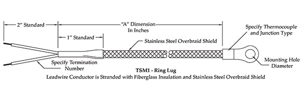 Figure 4: Surface mount thermocouple with mounting ring (Source)
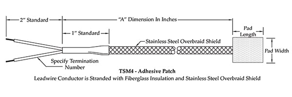 Figure 5: Surface mount thermocouple with adhesive patch (Source)
How to select a thermocouple setup
To successfully select the correct thermocouple for your project, it is imperative to answer a few basic questions:
- What environment will you be monitoring?
- What is your predicted temperature range?
- What is your desired sample rate?
- Are you are looking to record or simply monitor the temperature data
The information regarding your operating environment informs your options for sheath type. The thermocouples temperature range and sensitivity are dictated by the combination of alloys that make up the sensor (ex. J-type, K-type, etc.). Refer to Table 2 for a list of most common thermocouple types.
Table 2: Thermocouple types and properties (Source)
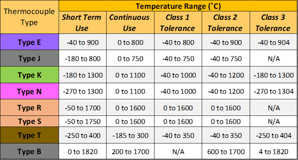
Note: Different types of thermocouple sensors have been mentioned up to this point for the purposes of education, however in this section and in general outside the context of this blog post when someone refers to a thermocouple type, they generally mean J-type, K-type etc. and not the type of sensor being utilized within the thermocouple itself. For further information on thermocouple types you can visit Omega.
Desired sample rate is determined by your need or lack of need to observe trends over a small or large time step. If the event is short or occurs periodically over a small time step, a sensor with a faster sample rate would likely make more sense as it would capture the details of that event. If the desire is to generally monitor temperature over time, then a less expensive sensor with a lower sample rate would likely suffice.
Finally and most simply, it must be determined whether you want to monitor and display your data in real time or record it for export for analysis. If you want to monitor your temperature and set alerts in real time, you can wire the leads from your thermocouple(s) into specialized thermocouple connectors that are shown below in Figure 6 then use a handheld digital thermometer made to receive thermocouple connectors - an example of which is shown below in Figure 7.
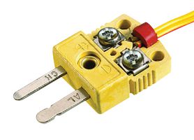
Figure 6: Thermocouple connector (Source)
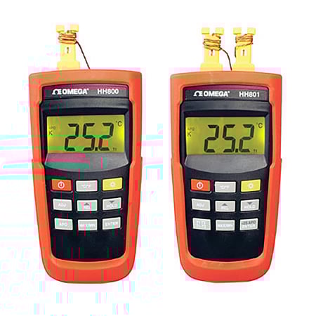
Figure 7: A common model handheld digital thermometer (Omega HH800) (Source)
If your project calls for monitoring and recording of data, the thermocouple(s) should be wired into a data acquisition card which is then plugged into a National Instruments (NI) chassis and interfaced with NI LabView software. We will not go into the details of the setup for this here as it is a complex and arduous process.
Where to buy
All of the components discussed in this blog are commercial off the shelf components that can be found at McMaster-Carr or your preferred authorized instrumentation dealer.
Case study
Bringing all of this together, we can step through the process to instrument a custom low heat-loss high temperature heat well created for the purposes of verifying a beta type Stirling engine prototype.
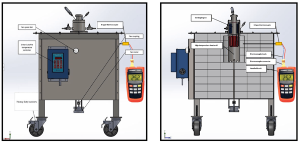 Figure 8: Diagram of a K-type Thermocouple installed in to monitor a high temperature heat well in a custom electric oven.
The general idea behind this project was to create a constant temperature heat well into which the hot end of a Stirling engine could be placed. Since the quantity of electricity that the heating element was putting into the system and the heat loss characteristics of the system at a range of temperatures were known, the energy transferred into the Stirling engine could be determined by comparing the steady state of the oven with and without the Stirling attached. Given that the power output of the Stirling engine was also a known, the efficiency of the Stirling engine could then be determined.
To select the correct thermocouple for this application, we looked at the environment that we needed to monitor; since it was the inside of what amounts to an oven and we were dealing with hot air as a working fluid - a probe type thermometer was selected.
The type of probe thermocouple depended on the temperature range we expected to see within the chamber and since the temperature within the chamber is a known - in this case it was 1100°C we were then able to refer back to the table of thermocouples to find a thermocouple that has a temperature range that includes that temperature. In this case we chose a K-type thermocouple.
In this case, sample rate was not a concern as we were monitoring temperature at infrequent intervals in order to check that the temperature controller was still functioning properly.
Installing the thermocouple was as simple as inserting the probe into the pre-drilled and pre-tapped hole in the side of the high temperature heat well. Once secured, the ends of the leads were wired into a thermocouple connector which was then plugged into a handheld thermometer that accepts thermocouple plugs - in our case we happened to use an Omega model HH800 meter.
With the thermocouple plugged into the handheld meter we were able to monitor the temperature of the high temperature heat well in real time.
Conclusion
I hope this blog has given you a good overview of the functions, types, selection, and application of thermocouples. If you have any other questions, don't hesitate to leave a comment or to contact us directly. And don't forget to subscribe to our blog for more helpful articles on data acquisition, sensors, and analysis.
Related Posts:
- Tracking Thermal Currents Through My Living Room
- Vibration Sensor Types and Where to Buy Them
- 4 Essentials When Choosing Data Acquisition Hardware
For more on this topic, visit our dedicated Environmental Sensors resource page. There you’ll find more blog posts, case studies, webinars, software, and products focused on your environmental testing and analysis needs.