Strain gauges are devices that are commonly used by engineers to measure the effect of external forces on an object. They measure strain directly, which can be used to indirectly determine stress, torque, pressure, deflection, and many other measurements.
In this post I’ll provide an overview on what strain gauges are and how they work. Then I’ll dive a bit deeper into the different types of strain gauges, provide some example applications, and then go through a detailed case study of one application where I work. If interested in buying a strain gauge to use in your project, I’ll also provide a few places to buy them.
- What is a Strain Gauge and How Do They Work?
- Types of Strain Gauges
- Where to Buy Strain Gauges
- Strain Gauge Applications
- Strain Gauge Case Study
- Conclusion
What is a Strain Gauge and How Do They Work?
Strain is a dimensionless measurement that is a ratio of the change in length to the original length of an object. Therefore, a positive strain is the result of stretching a material and negative strain is the result of compression. Stress is a measurement of the force applied divided by the initial cross-sectional area of an object, or the internal resisting capacity of an object.
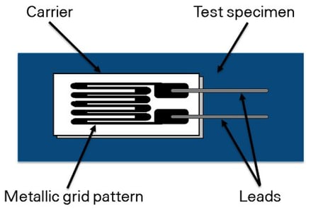
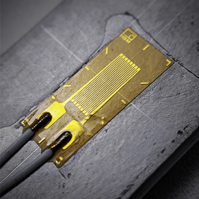
Figure 1. Left: Composition of a strain gauge (source) Right: Example of a strain gauge (source)
Each strain gauge is composed of a metal foil insulated by a flexible substrate, as shown in the figure above. The two leads pass a current through the gauge, and as the surface of the object being measured stretches or contracts, the change in resistance is measured. This change in resistance is proportional to the change in length on the surface of the object being tested, as shown in the equation below. Strain gauges work by measuring the change in electrical resistance across a thin conductive foil. The gauge factor (or “gage factor”) is the sensitivity of the strain gauge (usually 2). It converts the change in resistance to the change in length.
Equation 1: Gauge factor equation (source).
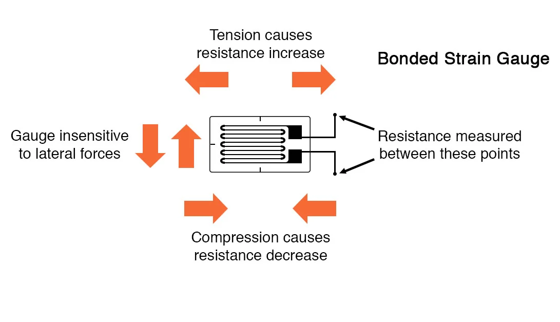
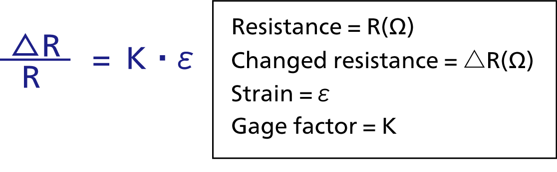
Figure 2. Compression and tension as experienced on a strain gauge (source).
As a strain gauge experiences bending, stretching, or twisting, the change in resistance across the metal foil is measured by a Wheatstone bridge. The change in resistance that is measured is proportional to the strain experienced by the object. A user can determine the stress experienced by an object using Hooke’s law (equation shown below) by knowing the material’s modulus of elasticity.
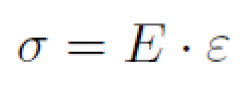
Equation 2: Hooke’s law equation.
Types of Strain Gauges
While there are many types of strain gauges--for different applications and the degree of freedom to be measured, all of them use a Wheatstone bridge to calculate the change in resistance.
Quarter Bridge Strain Gauge
If you are measuring a single axis, a quarter bridge strain gauge is used, as shown in the figure below. The quarter bridge refers to that fact that only one of the four resistors is variable (Rx) and the other three resistors are fixed. The circuit determines the value of the variable resistor so that the circuit is balanced and no current passes between points B and C.
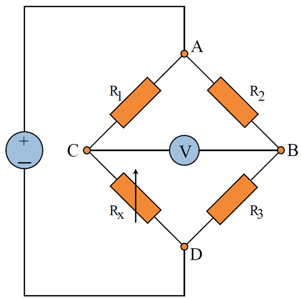
Figure 3. Wheatstone quarter bridge diagram (image source: copyright DEWESoft from their PRO Training Series).
Strain Gauge Rosettes
Some strain gauges called strain gauge rosettes use additional sensors to provide strain measurements in multiple directions. The rosettes are used to determine the complete strain state of an object at the surface. The complete strain state is composed of normal, shear, and principal strains. A biaxial rosette uses two sensors and the strain gauges are mounted perpendicular to each other. For a triaxial rosette, three degrees of measurement are necessary. These gauges are mounted at 0°-45°-90° or 0°-60°-120° relative to each other, depending on the measurements required. Below are some common configurations for strain gauge rosettes (you can see the original
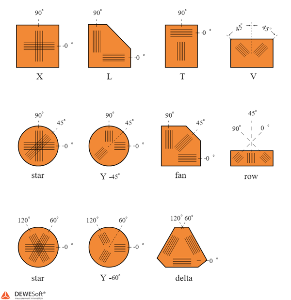
Figure 4. Strain gauge rosette examples (image source: copyright DEWESoft from their PRO Training Series).
Piezoresistor
When measuring strain that is on a small scale, a piezoresistor is often a better measurement tool. These measurements are often so small that they are expressed in micro strain (µε or ε x 10-6). When these sensors are used, the sensitivity changes so the gauge factor is often higher than a typical foil strain gauge. While these sensors record smaller changes in length, they are also more susceptible to temperature changes and are more likely to break than foil gauges.
Where to Buy Strain Gauges
If you are interested in using a strain gauge for your application, there are a variety of places to get them, here are just a few we use typically use:
Now with strain gauges you will also need very specific instrumentation to power and condition the signal output of a strain gauge. Here are a few options from HBM and more from Omega. We know many enDAQ customers are also interested in adding strain gauge measurement capabilities to our devices to go along with the accelerometers and other sensors and we plan to develop such a solution within the next couple of years (see more on our roadmap)!
Strain Gauge Applications
The fields of civil engineering and geotechnical monitoring regularly use strain gauges to detect failures in structures like bridges, buildings, and much more. These structures require constant monitoring because any significant deformation could lead to injuries or death. These gauges are commonly used because they have high precision, function well at long distances from the test object, and require minimal effort to set up and maintain over long periods of time.
Testing in the field is frequently quite different from laboratory testing under ideal conditions. One of the reasons strain gauges are highly valued is the fact that they can be used in harsh environments, yielding repeatable results with high precision. When an engineer tests objects with irregular shapes in harsh environments with difficult-to-access configurations, a specialized device like a strain gauge is often needed. For example, aerospace applications use millions of strain gauges to verify results from CAD (Computer Aided Design) and FEA (Finite Element Analysis) simulations. These tests are often conducted in dynamic conditions to display an accurate representation of how different forces affect aircraft.

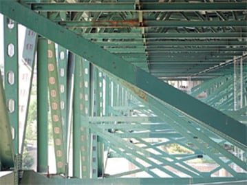
Figure 5. Left: Minneapolis steel truss bridge in 2006. Right: Underside of the bridge. (Source)
Strain gauges are also frequently used for static testing. Some bridges are set up to use wireless telemetry, which transfers the testing results via Ethernet. But other bridges primarily undergo visual inspection or penetrant testing to detect surface defects. While cost-efficient, these methods are without constant inspection, which can lead to catastrophic failures such as with the I-35 Minneapolis steel truss bridge. Beginning in 1990, the bridge was flagged as “structurally deficient” by the federal government, which meant that it had to undergo yearly inspections. However, in the absence of constant monitoring from strain gauges, significant repairs, or replacement, the bridge inevitably collapsed in 2007, killing 13 people. This bridge is just one of roughly 80,000 bridges across the United States that were found, in 2007, to be “structurally deficient.”
Strain Gauge Case Study
Here at Midé (Note: enDAQ is a division of Midé), we use strain gauges regularly for project work. Recently, a colleague and I added a strain gauge to our test setup to indirectly measure torque. The project we were working on focused on the design of a deep-sea diving suit. For this experiment, we tested the amount of torque required to rotate a thrust bearing in the arm of the suit by pressurizing the thrust bearing to simulate using it at a depth of up to 530 feet.
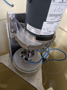
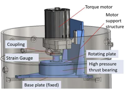
Figure 6.Test setup with the strain gauge mounted in between the motor and thrust bearing.
For this test, a strain gauge was mounted to a pedestal in between a motor and a sealed thrust bearing, as shown in the figure above. This assembly was placed inside a high-pressure tank, submerged, and pressurized. The motor was powered by AC current, which made the torque output consistent. The tests conducted measured the resistance of the thrust bearing to axial rotation in both clockwise and counterclockwise directions.
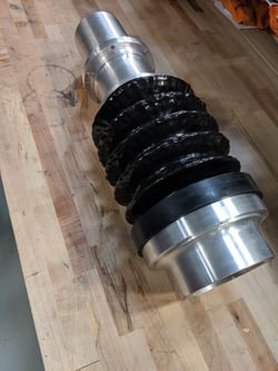
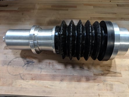
Figure 7. Fully assembled diving suit arm with thrust bearing.
During this test we slowly increased the pressure to determine the resistance of the thrust bearing at different depths. Starting with atmospheric pressure as a base, the pressure was increased to 30, 50, 75, 100, 150, 200, and 250 psig (or pounds per square inch). Each time we increased the pressure, the motor was rotated in both directions for 7-8 seconds. At the highest pressure, a maximum torque was measured by the strain gauge at 35 foot-pounds in the counterclockwise direction (positive torque), as shown in the graph below.

Figure 8. Torque vs. Time testing measurements using a strain gauge.
Conclusion
Strain gauges are profoundly versatile geotechnical tools with very broad applications that help to ensure safety and productivity. They are especially prized for their precision, ease of installation, low cost, long operating life, and the need for very limited maintenance. It is exciting to consider the many future applications of strain gauges in fields such as aerospace, cable bridges, rail monitoring (for railroad systems), and measuring torque and power in a wide range of rotating equipment such as fans, generators, wheels and propellers.
I hope this post helped you to better understand the different types of strain gauges, how they work, and their applications. If you have any questions, don't hesitate to leave a comment or contact us. And if you liked this post, don't forget to subscribe to our enDAQ blog for more on data acquisition, sensors, and analysis.
Related Posts:
- Meeting the Challenges of Conditions-Based Monitoring on Larger Wind Turbines
- Vibration Measurements: Accelerometer Basics
- Vibration Sensor Types and Where to Buy Them
For more on this topic, visit our dedicated Environmental Sensors resource page. There you’ll find more blog posts, case studies, webinars, software, and products focused on your environmental testing and analysis needs.