Measuring angular motion can be important in a wide variety of applications, including sports biomechanics and astronomy. In this blog post, I'll go over how to define rotation and what's needed to calculate angular velocity. I’ll then walk you through how to measure rotation and what’s required (including formulas) to calculate angular velocity with an accelerometer. There are a variety of accelerometers and DAQ systems that can help measure both orientation and acceleration, but for this post I’ll be using one of my company’s enDAQ sensors, as it comes equipped with in-built gyroscopes and accelerometers.
I'll cover:
- Reference Frames
- Orientation
- Quaternions
- Angular Velocity
- Acceleration
- Application to enDAQ Sensors
- Conclusion
- References
Reference Frames
In order to define rotation (and by extension angular velocity and acceleration) it is first necessary to define some terms:
Vector Basis
A vector basis is a set of non-coplanar vectors that are used to define orientation. Vector bases may have additional properties such as:
- Orthogonal - the basis vectors are mutually orthogonal. Orthogonal vector bases are also rigid by definition
- Normal - all of the basis vectors are unit vectors
- Rigid - the angles between the basis vectors are constant. This introduces a sense of time to the basis since time must be defined in order for the angles to not change over time.
Reference Frame
A reference frame is an infinite set of non-collinear points where the distance between any two points is constant. Once again, the term constant implies a sense of time. Reference frames define both position and orientation. A convenient way to define a reference frame N is using a point and an orthonormal vector basis fixed in N. Reference frames can be Newtonian or non-Newtonian:
- Newtonian Reference Frame - (also known as an inertial reference frame) a non-accelerating (this includes non-rotating) reference frame in which
 accurately predicts all motion. The Earth is a non- Newtonian reference frame, however it can often be approximated as a Newtonian reference frame.
- Non-Newtonian Reference Frame - an accelerating reference frame in which does not apply.
For the purposes of this guide, we will restrict our focus to 3D orthonormal vector bases. Orientation and its derivatives (angular velocity and acceleration) can be defined without specifying any points, so they can be defined in terms of a pair of vector bases. Since reference frames contain vector bases, orientation can also be defined in terms of two reference frames. Position and its derivatives (velocity and acceleration) are defined between two points, and thus require at least one reference frame to be defined.
Orientation
The orientation of a rigid body is defined by the alignment between a vector basis attached to the body and another vector basis or reference frame. For the purposes of this guide, we will consider the orientation of a body B (defined by orthonormal basis vectors  ) in the world reference frame W (defined by orthonormal basis vectors
  ). There are several ways to define the orientation of B in W.
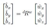
- Rotation Matrix - the rotation matrix bRw which is defined such that:
- Euler Angles - successive rotations about the b basis vectors. These rotations can be performed in any order such as XYZ or YZY .
- Euler Parameters (Quaternions) - Any rotation(s) that can be expressed using either of the two preceding methods can also be expressed as a single rotation θ about the unit vector
 . is fixed in both W and B for this rotation and θ is the angle between two arbitrary vectors
  (fixed in W) and
  (fixed in B) which are initially equal. It should be noted that is fixed for this rotation only, and is not guaranteed to remain fixed for subsequent rotations. Rotation using Euler parameters can be conveniently expressed and efficiently computed using quaternions.
Conversion between these forms can be accomplished using the formulas found in this NASA Technical Brief [2].
Quaternions
A quaternion is a hypercomplex number of the form
 |
(1) |
where
 |
(2) |
For the purposes of this document, quaternions will be expressed in bold font. A more convenient way to express (1) is as the sum of a scalar and a vector
 |
(3) |
There are several properties and definitions of quaternions that will be relevant to this analysis.
Table 1: Quaternion Properties and Definitions
| Name | Symbol | Definition |
| Quaternion Conjugate |  |
|
| Quaternion Norm |  |
|
| Unit Quaternion |
|
|
| Pure Quaternion |  |
|
| Quaternion Sum | a + b |  |
| Quaternion Product | ab |  |
| Quaternion Time Derivative |  |

As mentioned previously, quaternions are a convenient way to express Euler parameters (![]() rotations). This can be done by re-writing (3) as the unit quaternion
rotations). This can be done by re-writing (3) as the unit quaternion
 |
(4) |
Suppose that ![]() is a vector in the body basis B.
is a vector in the body basis B. ![]() can be expressed as the pure quaternion
can be expressed as the pure quaternion
 |
(5) |
Suppose also that the transformation between the body basis B and the world frame W is achieved by the rotation of θ about ![]() , expressed with the unit quaternion q as defined in (4). Transforming
, expressed with the unit quaternion q as defined in (4). Transforming ![]() into the world frame W can be done using
into the world frame W can be done using
|
(6) |
This operation is known as a frame rotation, because the reference frame is rotating and the vector itself is unchanged. A proof for this relation can be found in [3].
Angular Velocity
The angular velocity of the body B expressed in the world frame W is denoted as ![]() . When working with
. When working with ![]() rotations, it is tempting to express the angular velocity of the rotating frame as
rotations, it is tempting to express the angular velocity of the rotating frame as
 |
however, this is only valid if ![]() remains fixed in both frames! If
remains fixed in both frames! If ![]() is changing, the angular velocity is
is changing, the angular velocity is
 |
(7) |
 |
(8) |
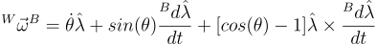
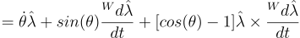
the proof of which can be found in [4]. Since ![]() is a vector, it must be differentiated in a reference frame (or vector basis). It turns out that the time derivative of
is a vector, it must be differentiated in a reference frame (or vector basis). It turns out that the time derivative of ![]() is the same in both the world frame and body basis. Using (4), (7) can be written as
is the same in both the world frame and body basis. Using (4), (7) can be written as
 |
(9) |
where  . This equation can be proven a number of different ways [1][3]. When solving (9) numerically, the real part of
 ![]() may be nonzero, however this can be ignored to a reasonable approximation.
may be nonzero, however this can be ignored to a reasonable approximation.
Acceleration
In addition to calculating the angular velocity, quaternions can also be used to transform the accelerometer data between reference frames. Acceleration is derived from position, and thus must be defined in a reference frame as opposed to a vector basis. The most convenient way to form a reference frame in this case is with a point and a vector basis. The choice of this point is arbitrary, as the acceleration of one reference frame in another does not depend on the absolute distance between any two points. Any vector, such as acceleration, can be transformed from one reference frame to another using Equation (6).
It should be noted that the world reference frame is a non-Newtonian reference frame due to the rotation of the earth. This effect may or may not be relevant to your measurements, depending on the application and length of data acquisition.
Application to enDAQ Sensors
enDAQ sensors feature an IMU unit that outputs orientation in the form of an array of quaternions. These quaternions provide the enDAQ sensor vector basis D (defined in Figure 1) in one of two possible reference bases at each data acquisition point.
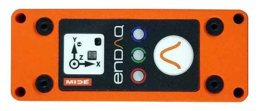
Figure 1. enDAQ S4 Sensor with basis vectors labeled
The two possible reference bases are related to how the orientation is calculated by the IMU:
- Absolute Orientation - The orientation is calculated using the gyroscope with corrections from the accelerometer and the magnetometer. The reference basis is the world basis, W, which is formed by
 pointing North,
  pointing opposite the gravity vector, and
  forming a right-handed system
 - Relative Orientation - The orientation is calculated using the gyroscope with corrections from the accelerometer only. The reference basis D0 is coincident with the enDAQ sensor basis D at the first data acquisition point
More detail on the advantages and disadvantages of these two systems can be found in this enDAQ blog post: Quaternions for Orientation.
The gyroscope in the IMU measures the angular velocity and then integrates to find the orientation. This means that we can differentiate the orientation to find the angular velocity without worrying about amplifying the noise. Figure 2 compares the angular velocity calculated using (9) and the angular velocity measured directly by the IMU. It should be noted that the IMU in the enDAQ sensor cannot simultaneously provide the orientation quaternion and the raw IMU angular velocity, so the data in Figure 2 was taken by two enDAQ sensors mounted to the same rotating surface. The slight variation between them is a result of differing noise levels, as well as imperfections in the cross-correlation of the two signals.

Figure 2. Angular velocity calculated by differentiating the quaternion and pulled directly from the IMU
Acquiring Angular Velocity and Acceleration from an enDAQ Sensor IMU
- Format the enDAQ sensor by selecting absolute orientation or relative orientation.
- Acquire the data.
- Numerically differentiate the quaternion array to find
 using
using These lecture notes give a good overview of finite difference methods of numerical integration.
 - Calculate the angular velocity and acceleration of the enDAQ basis D in the reference basis A (where A is either the world basis W or the initial reference basis D0) numerically using Equation (9) and Table 1.

where .
. - The reference basis that you chose may not be the most convenient for expressing the angular velocity, so it can be transformed into a new basis N using
 where q is the quaternion that describes the transformation between A and N.
Transforming enDAQ Sensor Acceleration Using Quaternions
The quaternion array can also be used to transform the acceleration data from the rotating enDAQ sensor reference frame into a stationary reference frame at each data acquisition point using

where  , D is the enDAQ reference frame and A is either the world reference frame W or the initial reference frame D0 depending on if the unit is in absolute or relative position mode.
Conclusion
So that is your overview of angular motion and how to use an enDAQ sensor to measure rotation and angular velocity. I hope you found it helpful. For more content like this, don't forget to subscribe to our blog and if you have any questions, don't hesitate to leave a comment below or contact us directly.
Related Posts:
- Quaternions for Orientation
- Vibration Measurements: Accelerometer Basics
- Frequency Leakage in Fourier Transforms
For more on this topic, visit our dedicated Environmental Sensors resource page. There you’ll find more blog posts, case studies, webinars, software, and products focused on your environmental testing and analysis needs.

References
[1] Basile Graf. "Quaternions and Dynamics". en. In: arXiv:0811.2889 [math- ph] (Nov. 2008). arXiv: 0811.2889 [math-ph].
[2] D M Henderson. "Euler Angles, Quaternions, and Transformation Matrices". en. In: (1977), p. 42.
[3] Yan-Bin Jia. Quaternions. Sept. 2019.
[4] Paul Mitiguy. Advanced Dynamics and Motion Simulation. 2015.