I have been working away on some big stuff: we are releasing a new sensor package for the enDAQ sensor (formerly known as Slam Stick)! The next sensor release will include an IMU (Inertial Measurement Unit) on the device, which can put out either orientation or rotation data. This sensor is very different from anything on the enDAQ sensor today, and it really expands the sensor’s capabilities. This post focuses on the directional or orientation measurements, which are put out as quaternions, and I will have another post to talk about the rotation measurements.
Absolute vs Relative Direction
There are two options for the orientation sensor: absolute and relative. The absolute measurement provides a rotation relative to magnetic north, and the relative measurement is the orientation relative to the orientation the sensor had when the acquisition started. Both sensors work by integrating the rotation, and applying a correction factor from the accelerometer, including a detection of the gravity vector. The absolute orientation sensor also uses the magnetometer to orient itself to the magnetic field.
There are a few subtle points to note. Since the absolute orientation sensor uses a magnetometer, it can be better at detecting slow turns, which result in a low rate of degrees per second applied over a number of seconds. Similarly, it should be less likely to drift over long periods. But, since the absolute measurement uses a magnetometer, it increases the power draw (about 10% higher on a SSC, or under 5% on a SSX, and less on a SSS, depending on your exact measurement setup). The absolute sensor also require some movement before the sensors all lock on for high accuracy data. Learn how to get high accuracy data.
The relative orientation measurement simply takes its orientation at startup, when the first sample is taken, as its unrotated orientation, and all other measurements are relative to that. The relative measurement uses the accelerometer and gyroscope, so there is no magnetometer to give an absolute feedback. This means that there is no accuracy information, not necessarily because the relative measurement is more accurate, just because there is no absolute reference it can measure its accuracy against.
So, to sum it up, the absolute direction, when fully calibrated, will read w:1, x:0, y:0, z:0 when the X axis faces north, and the relative direction measurement reads w:1, x:0, y:0, z:0 at its first acquisition.
Quaternions and What They Mean
The main thing I have learned from using quaternions recently is that quaternions are a very unintuitive system. There is at least one book written about visualizing quaternions, there are a few good guides around the internet, and Wolfram Alpha has a handy tool for visualizing quaternions. I recite some equations and give some tips on the Wolfram Alpha tool at the end, but first I want to go into some tips I wish I had when I started learning about quaternions.
Most discussions of quaternions use them for rotation, but the enDAQ sensor uses them to show its orientation. Most discussions do not mention the quaternion of w:1, x:0, y:0, z:0, because it does not describe any rotation. Translate it into a rotation matrix, and you get identity. The Wolfram Alpha tool does not even recognize that value as a quaternion. That is why the enDAQ sensor in relative direction mode returns w:1, x:0, y:0, z:0 for its first reading, because it has no rotation to describe.
The video below shows the sensor being rotated around each axis. At first, we are in the unrotated state of w:1, x:0, y:0, z:0. As we rotate the sensor around X, the quaternion for X will start to increase, and the W will decrease. The sensor provides unit quaternions, so the sum of the squares is always one. When we rotate 180 degrees, X is now at 1, and W is at 0. We keep rotating, and X goes back to 0, but W continues its decline to -1. Next we rotate around the Y axis. Y is in light green and a bit tough to see, but the value for W starts to increase towards 0 while Y increases to reach 1 when it is at 180 degrees, and then when it has returned to the original orientation, W is at 1, and all other coordinates are at 0. When we rotate around Z, it goes down to the -1 instead of +1, but otherwise the motion looks like what we have seen before.
So what is going on here? Why do we sometimes reach +1 and sometimes -1? A quaternion and its inverse refer to the same orientation, so x:+0.7 y:0 z:0 w:+0.7 == x:-0.7 y:0 z:0 w:-0.7 (but that is a different rotation from x:-0.7 y:0 z:0 w:+0.7). In the below example, I rotate around the X axis 3 times, and you can see the quaternions make a nice, smooth sinusoidal wave between +1 and -1. This is one of the benefits of quaternions over Euler angles, an Euler angle would have to wrap around from +180 to -180 at some point. The image below shows the full quaternion plot with a plot of the corresponding Euler angles.
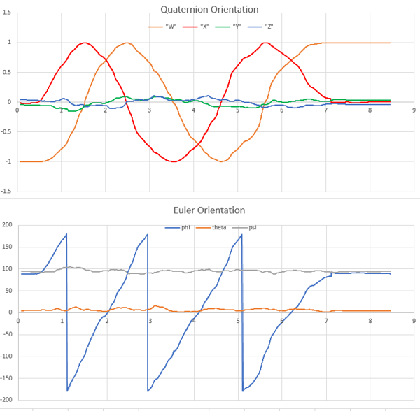
We can see from the Euler angle, that we start off at 90, 0, 90. When we rotate 90 degrees to 180, 0, 90, the quaternion has W=-0.7, X=0.7. Then the Euler rolls over to -180, and after 90 more degrees, when the Euler is at -90, 0, 90, the quaternion is at W=0, X=1. This graph does show a bit of a jump at the end, which is the sensor adjusting its position based on its reading of gravity through the DC accelerometer.
Is there anything we can learn from the sign of the quaternion? Yes and no. The simplest statement is that if a quaternion goes to the same orientation twice without going through its inverse (eg it goes from W=1 to W=0, then back to W=1 without reaching W=-1), then it has retraced its path to some degree, for example it rotates 180 clockwise around the X axis, and then rotation 180 counter clockwise, as in the example below. There are deeper statements we can make, but they start to get complicated once we rotate over more than one axis, so I will hold off for now.
So we know that the values of X, Y, and Z correspond to rotations about that axis in the original frame of reference. What if we rotate 180 degrees around X, then 180 degrees around Y? It turns out, you end up with a coordinate of w:0, x:0, y:0, z:1. The reason for this is obvious once you try it out, because the rotation we tried is equivalent to rotating around the Z axis. Mathematically, it falls out of the ijk representation of quaternions, where i*j = k, but there are other sources that explain this in more detail.
The main part to note here is that the beauty of quaternions is that you cannot trick them, they will indicate your orientation in the clearest way. This is their most important differentiation from Euler angles, where you can get into gimbal lock, where the system does not have freedom in all three dimensions when two of the angles are aligned.
Before I go, a few words about Wolfram Alpha’s use of quaternions. You can visualize a quaternion’s rotation by going to Wolfram Alpha, and entering “quaternion: W + Xi + Yj + Zk”, where W, X, Y, Z are all numbers, but I, j, k are the letters. I have found the 3D transformation window to be very useful, especially after you push the “graphs separated” button. The second graph, a red R, corresponds to the orientation of the enDAQ sensor, and the blue line in that graph is the axis around which it was rotated. The Corresponding 3D rotation window, just below, uses a big red line to indicate the axis of rotation, and I wasted a lot of time expecting that to correspond with the orientation of the sensor in some direct way.
As I said earlier, quaternions are a tough but very powerful tool. Using quaternions, you can generate a rotation matrix, apply that matrix to the acceleration output, and see your acceleration relative to an absolute orientation. With the absolute orientation, you can isolate the vibrations and accelerations your car goes through when it turns. You even can trace out the twists and turns of an object as it moves through space. I think this sensor opens up some new possibilities, and I'm excited to see what people use it for.
Useful Equations
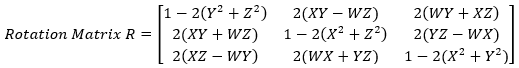
To apply quaternion rotation to cartesian coordinates, just multiply the cartesian coordinates by the rotation vector:
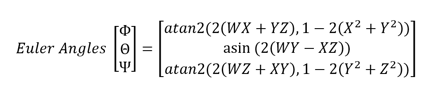
To get Euler angles, which are a bit more intuitive, you can refer to code on Wikipedia, or use:
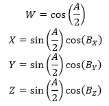
The following equation shows the interrelationship between W, X, Y, Z to the rotation about the respective axes (Bx, By, Bz), and A, which is the angle of rotation needed if the rotation were taken in one go around a single fixed axis, chosen for the specified orientation. Note that Bx, By, Bz are direction angles, and the sum of the squares of the cosines must be one. I think of these angles as describe the angle from an axis to an imaginary vector pointing in the direction of orientation. If these angles are used correctly, the sum of the squares of W, X, Y, Z will be 1.
Download Excel Conversion
For many of our enDAQ customers that have a device which records orientation in quaternions I also put together an Excel file that can convert the exported quaternions and convert to Euler angles.
For more on this topic, visit our dedicated Environmental Sensors resource page. There you’ll find more blog posts, case studies, webinars, software, and products focused on your environmental testing and analysis needs.