Cliffs and Gorges.. Building an Analog Low-Pass Filter
This is the fifth in a series of blogs on the basic concepts of digital data acquisition. In the first blog we talked about how different data acquisition strategies give us different, but equally right (or wrong) results. In the second, we discussed sampling basics and \aliasing and the irrecoverable errors they cause, and in the third we got started on the discussion of what filtering and sample-rate strategies are necessary to reduce aliasing errors to “acceptable” levels. The fourth, covered the pros and cons of the filter types for that we might use for alias protection. Here, and in the next one, we will discuss the hardware concepts needed to accomplish these objectives.
Philosophy.. Keep it Simple
We are going to discuss the strategies used to design useful analog low-pass filters from basic building blocks. We are not going to stray very far into the unknown so we won’t have to worry about stability and such. I hope that won’t offend our more-mathematically-inclined readers.
So, Let's Build Some Filters
As soon as Shannon and his co-researchers discovered the basic concepts and problems associated with digital data measurements, solutions to the aliasing problem appeared. Analog low pass filters were developed that attenuated the energy above the Nyquist Frequency (FN) and consequently reduced aliasing. Later, when computing power increased, digital filters joined the fray.
So, let’s get started with analog filters… We will do the hybrid/digital (SD) flavor next time.
Poles... the Basic Building Blocks
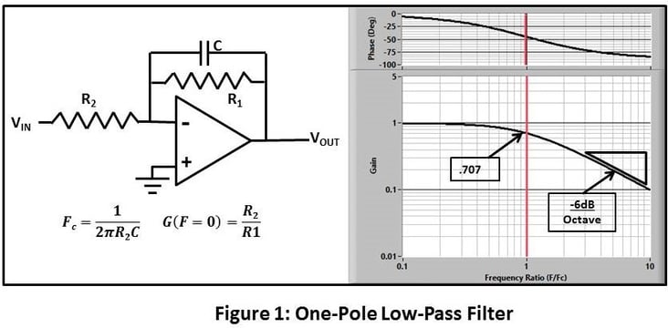
Figure 1 shows the operational-amplifier circuit diagram and transfer function of a one-pole filter. Its features/characteristics are:
- Its cutoff frequency (FC ,where attenuation= 3dB, gain ~ .707) and low-frequency gain are controlled by the resistors and capacitors in the circuit.
- I rolls off at -6dB/octave = -20dB/decade (which is a fancy way to say that its high-frequency attenuation is directly proportional to frequency).
- The phase (lag) is zero at zero frequency, passes through 45 degrees at FC, and approaches 90 degrees at high frequency.
This is not sharp enough to be useful as an anti-alias filter, Maybe we could put a bunch of them in series to make a multi-pole filter. The result of stringing 4 of them in series (which results in the multiplying of the transfer functions) is shown in Figure 2.
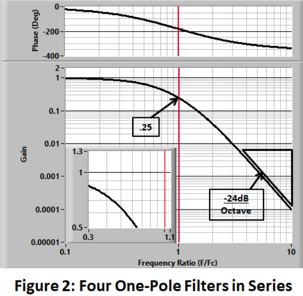
At high frequency, it rolls of 4 times a fast (good) but its attenuation (amplitude distortion) in the pass band (below FC) is pretty bad. We can do better.
Let's take a break here to ask you to join the discussion.
With any luck, I have provoked some questions and/or disagreements in these blogs.
For instance, the first blog generated a comment/question about my statement that I dislike Bessel filters. I think that answered that in the previous entry. Do you agree?
At the bottom of the page you will find ways to contact me.
The Two-Pole Circuit to the Rescue
Fortunately there is a better tool. Figure 3 shows the basic circuit and transfer functions of several two-pole filters with different damping.
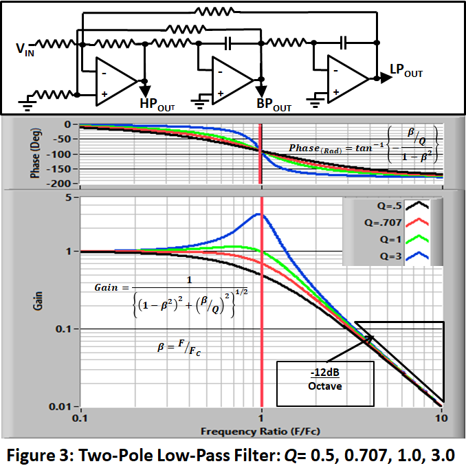
The critical features are:
- In addition to being able to adjust the cutoff frequency (FC), we can also control the “peakiness” (Q) of the transfer function. The figure shows the amplitude and phase characteristics for different Qs (0.5, 0.707, 1.0, and 3.0.).
- At frequencies well above FC they all roll off at -12dB/octave.
- The phase starts at 0 and passes through 90 degrees at FC on its way to 180 degrees at infinite frequency. Higher Qs make the phase change more rapidly near FC.
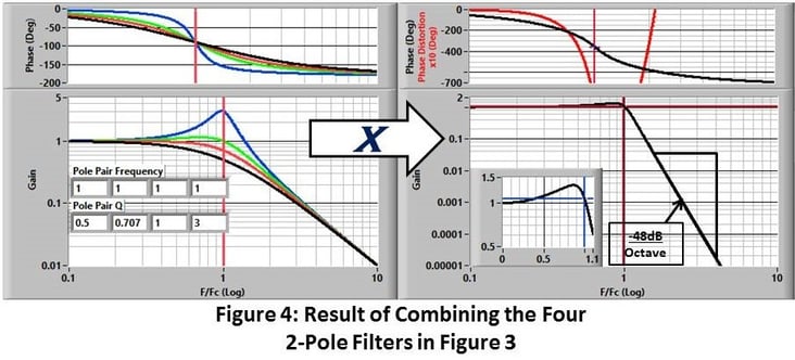
If we put several of these circuits in series we can build a multi-pole filter. For example if we were to combine the four 2-pole circuits in Figure 3 to make an 8-pole filter, we would produce the transfer function in Figure 4. Its attenuation rate at high frequency is -8 x 6 = -48dB/Octave and it is pretty flat in the passband (<FC). Not a bad low-pass filter but we can do better.
That’s the basic idea. Adding more (appropriately configured) poles (and zeroes, as we will see shortly) will produce a sharper filter. Figure 5 shows the effect of adding more poles.
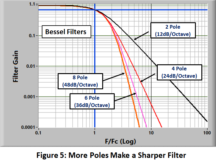
Each pole increases the roll-off slope by 6dB/octave and provides more high-frequency attenuation.
It’s as simple as that, or is it?
How do we design a filter that meets our needs? Fortunately, smart people have been here ahead of us.
In 1930 Stephen Butterworth designed a family of filter sets named for him and in 1949 W. E. Thompson applied Bessel functions to manipulate the filter coefficients to produce a "Bessel" filter set with different desirable characteristics. These have become standards in the industry.
The designs of 8-pole Bessel and Butterworth filters are shown in Figure 6.

The left frame shows the individual transfer functions of the four two-pole stages. The frequencies and Qs of the stages are shown in the lower left corner. The right frame shows the end result: the product of the individual stages that is produced by putting the four circuits in series. The inset in the lower left shows an expanded view of the filter pass band.
Comparison of the two strategies shows:
- Both designs roll off at 48 dB/Octave at high frequency
- The Butterworth design uses stages at lower frequency and with much-higher Q. This produces a flatter pass-band response and roll-off at lower frequency.
- The combination of poles and zeroes in the Bessel design produces constant delay/linear phase (See discussion in the fourth blog).
These filters represent the useable state of the art until about 1975.
Then Came Zeroes
In the late 70’s a new kind of filter surfaced that included “Zeroes”. A zero may be created by inverting the zero-damping, two-pole, response to produce the transfer function shown in Figure 7.

Its fundamental characteristics are:
- The gain well below FC is 1.
- The gain is ~0 at FC
- The gain slope well above FC is +12db/Octave. It is infinite at infinite frequency.
- The phase shifts 180o at FC.
Here we need to handle some strange nomenclature. It takes a two-pole circuit to make this filter shape. So it counted as two zeroes!
To make a filter, zeroes need to be combined with pole pairs to reduce the gain at high frequency. A useful filter must have and equal, or greater, number of poles than zeroes.
Enter Elliptical Filters
Filters that have zeroes are called Elliptical.
Figure 9 shows the characteristics of an 8 pole/8 zero elliptical filter that is optimized for alias rejection characteristics. It was offered by Tustin Electronics (R.I.P.) in the mid 1980’s.

Its fundamental characteristics are:
- It has a ripple of .5% P-P in the passband (Passband ripple is a characteristic feature of elliptical filters).
- It rolls off very fast to a ripple peak of -84dB (15848/1) at F/FC=1.5. The F/FC for an attenuation of 1000/1 is 1.41. By the rules described in a previous blog, this would allow a minimum Sample Ratio S/FD = 2.41.
- The phase is really goofy above the cutoff (where it doesn’t really matter).
Note that I have not listed the attenuation rate of the filter because it does not mean much. The critical feature is the frequency ratio at which the attenuation is adequate.
The Tustin filter has remarkable characteristics that are not likely to be found in modern systems. The critical feature is the Pole Pair with a Q>10. This is very hard to achieve for practical reasons. These systems were built by elves with tiny screwdrivers.
This filter is an example of using zeroes to provide “optimum” alias-rejection performance. The use of zeroes and poles also offers options to optimize other characteristics. Examples can be found here.
An in-depth analysis of the performance and usefulness of all of these filters can be found in the previous blog.
The next blog will cover the next generation of alias-protection systems: Hybrid Oversampling and Sigma Delta (SD) filters.
References
The following web pointers will give you more information and, in some cases, a different view of the low-pass filtering operation.
https://en.wikipedia.org/wiki/Bessel_filter
https://en.wikipedia.org/wiki/Butterworth_filter
https://en.wikipedia.org/wiki/Elliptic_filter
http://www.analog.com/media/en/training-seminars/design-handbooks/Basic-Linear-Design/Chapter8.pdf
http://www.electronics-tutorials.ws/filter/second-order-filters.html
http://www.pfinc.com/paper_briefs/anti_alias_brief.pdf
http://www.freqdev.com/guide/analog.html
https://www.maximintegrated.com/en/app-notes/index.mvp/id/733
Send a Comment or Question to Strether

One of the reasons I've been writing these blogs is to get a discussion going. Please reach out to me with any questions or comments you may have.
You can participate by:
- Entering comments/questions below in the Comments Section at the end of the blog. This will obviously be public to all readers.
- Contact me directly. I will respond privately and (hopefully) promptly. If appropriate, your question could be the subject of a future blog.
This blog is meant to be a seminar... not a lecture. I need your help & feedback to make it good!
Disclaimer
Strether has no official connection to Mide or enDAQ, a product line of Mide, and does not endorse Mide’s, or any other vendor’s, product unless it is expressly discussed in his blog posts.
Additional Resources
If you'd like to learn a little more about various aspects in shock and vibration testing and analysis, download our free Shock & Vibration Testing Overview eBook. In there are some examples, background, and a ton of links to where you can learn more. And as always, don't hesitate to reach out to us if you have any questions!