You can't get far in vibration testing and analysis without running across and benefiting from a power spectral density (PSD). PSDs, as the name implies, are used to analyze the vibration environment in the frequency spectrum, but FFTs do that, too. So what is it about PSDs that make them so ideal for vibration?
After reading this article I want you to not only understand what a PSD is, but know how and why you can use it to improve your vibration testing & analysis. Throughout the post I'll use data that can be downloaded here and our free software tool, VibrationData Toolbox, to generate the plots. I'll cover:
- What is a PSD?
- Comparison to an FFT
- Benefits & Features of a PSD
- Tool to Calculate a PSD
- Additional Resources
By the end of the article you will be able to understand how to effectively utilize PSDs to quantify a vibration environment and have the tools to go out and calculate one for your own vibration testing! And if you want to see more examples and benefits of the PSD for vibration analysis, check out our post Top 12 Vibration Metrics to Monitor & How to Calculate Them.

What is a Power Spectral Density (PSD)?
Vibration in the real world is often "random" with many different frequency components. Power spectral densities (PSD or, as they are often called, acceleration spectral densities or ASD for vibration) are used to quantify and compare different vibration environments. Engineers will see PSDs used in test standards such as MIL-STD-810 and others that provide guidance on how to qualify new products & systems for various operational and transportation environments.
I don't want to belabor the math that goes into a PSD (we have our handbook for that!). To illustrate what a PSD is, let's dive into some data! Here are vibration profiles in the time domain over 1 minute for a few different environments:
- NAVMAT (temperature and random vibration screening for Navy contractors)
- Jet Aircraft from MIL-STD-810 (another test standard for military applications)
- Highway Truck from MIL-STD-810
- Rail Cargo from MIL-STD-810
- Shipboard from MIL-STD-810

Looking at this data in the time domain can tell us that the vibration in a jet is likely more severe than rail. But that's only determined from looking at the peak amplitude which isn't always a good indicator. And it doesn't tell us where that energy lies... or what the power density is - that's why we have the power spectral density!

Here you can see that the PSD plots power (g2 / Hz) in the y axis as a function of frequency (Hz) in the x axis. In this format, we can clearly see the distinction between the vibration environments. So what is this g2 / Hz thing?
To answer that question, let's define how a PSD is calculated. The power spectral density function XPSD(f) is calculated from the discrete Fourier transform X(f) as

The one-half factor is needed to convert the amplitude from peak2/Hz to rms2/Hz which highlights another benefit of PSDs we'll explore later on.
The frequency step is finite in practice and is the inverse of the total measured duration.

This frequency step is the smallest sine wave frequency which can be resolved. A wider Δf gives greater PSD confidence in terms of smoothing the spectral components. For more of a technical discussion on what a PSD is, visit our learn article with a handbook download available.
Difference Between PSD and FFT
Although engineers are tempted to use FFTs (fast Fourier transforms) for spectrum analysis, they should really be using (PSDs) power spectral densities. The reason is that PSDs are normalized to the frequency bin width preventing the duration of the data set (and corresponding frequency step) from changing the amplitude of the result. FFTs don't do this!
Let's take that same data from the jet standard and calculate and plot FFTs for different time lengths. Check out how the longer the time series is (and the finer the frequency bin width/step is), the lower the amplitude of the FFT becomes! This means you can't really use FFTs to compare and quantify vibration environments.

Now let's do that same calculation for the PSD. In this plot I've kept the frequency bin width the same at 8 Hz. These different time lengths do nothing to the amplitude of the resulting PSD because they are normalized to the bin width.

The previous plots, and rest of the article will focus on typical vibration environments that have a broad range of frequency components. But there are some applications where there are very specific frequencies contributing to the signal such as when looking at machinery with rotating equipment. Let's construct a hypothetical waveform of broadband noise with a 0.5g 60 Hz and 100 Hz sine tone on top. This waveform is sampled at 10 kHz for 100 seconds.
Calculating a FFT at varying lengths shows significant change in the noise floor, but admittedly the amplitude at the peaks seems consistent.

But zooming in on that we can see it is still a little erratic depending on where that bin falls in relation to the pure 60 Hz sine.

Meanwhile the PSD between the different lengths looks identical.

Even zooming in there is still some modest change in amplitude but it isn't as significant as the FFT. Note how I was able to keep the bin width consistent between all the different time lengths which I'll discuss next as a major benefit of power spectral densities.

Benefits and Features of PSDs
Adjustable Bin Width to Smooth
You probably noticed in the last section how amazingly clean those PSD were! This is another major benefit of PSDs because they are dependent on that frequency bin width. You can manipulate this to smooth a PSD. The VibrationData Toolbox has a great feature that I highlight in our article on generating a PSD test standard. Here I highlight how changing that bin width from a very fine 0.02 Hz to 4 Hz will drastically smooth the PSD while keeping the overall energy in each frequency accurate and consistent across the whole range.


Root of Area under a PSD Equates to gRMS
Taking the square root of the area under a PSD will yield the RMS vibration level. To calculate this area requires special integration formulas due to the log-log format of PSD plots. First you need to calculate the slope N between each segment:

The area ai for a segment is then:

And finally the overall level for m total segments is then:

Using the previous set of PSDs on the jet cargo vibration environment we can compare the cumulative RMS for the different bin widths of 0.02 Hz and 4.3 Hz. This calculation of the RMS level from the PSD is conveniently done in the VibrationData Toolbox. Although the PSD with the smaller bin width is far nosier, when calculating the gRMS from the respective PSDs (root of area under curve) the two track each other nicely.
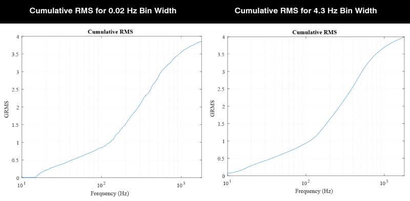
Calculating this cumulative RMS is also a helpful way of seeing which frequency components are contributing most of the acceleration amplitude.
Integrating an Acceleration PSD to Velocity & Displacement
Another helpful feature of PSDs is how easy it is to then convert an acceleration PSD to a corresponding velocity PSD and a displacement PSD. Let:
- APSD = Acceleration PSD
- VPSD = Velocity PSD
- DPSD = Displacement PSD
The integration formulas are:


Performing this calculation is a helpful and robust way to understand the velocity and displacement aspect of your vibration environment which can inform design decisions. The following are the velocity and displacement PSDs from the jet cargo MIL-STD-810.


Now let's bring back the other test standards to compare their corresponding velocity and displacement PSDs.


This highlights an obvious benefit of using PSDs... not all frequencies can be treated equally! The vibration environment for rail cargo looks less severe than the jet environment. But by recognizing the lower frequency density of the rail environment, you can predict it will introduce higher velocities and displacements than the jet environment. Let's bring back the time domain of both the jet and rail environment:

Here one would say that the jet aircraft has a more severe environment, but when we look at the velocity environment they have a similar amplitude. And kinetic energy is proportional to velocity squared, so we should arguably be more concerned with this when worried about fatigue.

And now when we convert all the way to displacement we can see just how much "stronger" that rail environment is!

Tools to Generate a PSD
Capture Vibration Data
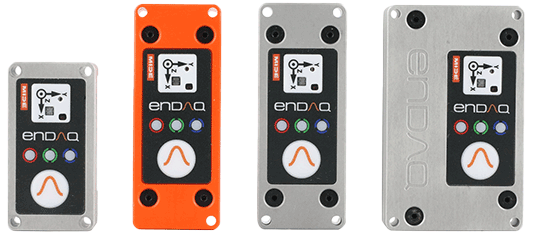
You'll need some acceleration time series data to use to calculate your own PSD. In order to get that data you can use some traditional accelerometers (see our article on accelerometer types and where to buy them) or you could consider a vibration data logger (see our article on the top 11). Pictured here are our portable and multifunctional enDAQ sensors that were designed to be brought out into the field to quantify vibration environments!
Calculate the PSD with Free Software
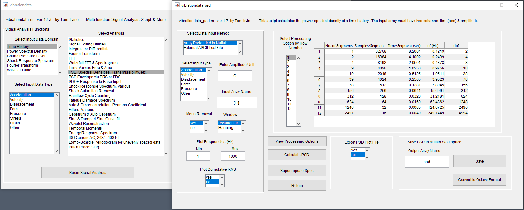
All of the plots in this article were generated using our VibrationData Toolbox. You can download this software directly from our website. We also have a dedicated VibrationData Toolbox section in our Help Center with user guides to help you use this software to its full potential. Pictured here is the dialog for calculating PSDs off time series vibration data where it also enables you to set the desired frequency bin width.
Conclusion & Additional Resources
I hope this article helped you better understand how to effectively utilize PSDs to quantify a vibration environment and that you now have the tools to calculate one for your own vibration testing. Here's a quick-hitting summary of the key points!
- PSDs are preferred to FFTs for vibration analysis because they are normalized to their bin width allowing you to compare PSDs between environments, test instrumentation, settings and duration and ensure you are comparing apples-to-apples!
- Once you have the PSD there are a lot of different follow-on analysis steps that can be done relatively easily such as:
- Converting to velocity or displacement
- Calculating vibration response spectrums to inform your design decisions
- Reproducing the environment on a shaker system
For more information on how to develop clean PSDs, check out my blog on How to Develop a Vibration Test Standard from Experimental Data. And to see the source code to generate a PSD in Python as well as generate some of the features discussed in this post, check out our article Top 12 Vibration Metrics to Monitor & How to Calculate Them.
Please don’t hesitate to leave a comment or contact us directly with any questions you may have on this topic or others. We are here to help you with all your testing needs!
Related Posts:
- How To Develop a Vibration Test Standard PSD from Experimental Data
- Vibration Analysis: FFT, PSD, and Spectrogram Basics
- Your Best 7 Options for Vibration Analysis Programming
For more on this topic, visit our dedicated Vibration Loggers & Vibration Sensors resource page. There you’ll find more blog posts, case studies, webinars, software, and products focused on your vibration testing and analysis needs.