Ever wonder what happens to your package or product during a shipment?
I'm not talking about how many times it was dropped or what the max "g-force" was. I want to know the vibration environment the package saw. I want to know not only the maximum acceleration, I want to know the pulse width of that shock event. I want to see the raw accelerometer data so that I can use my vibration shaker in the lab and replicate the shipping environment.
So I used one of our enDAQ (formerly Slam Stick) shock and vibration recorders to monitor what happens during a UPS ground shipment and during a UPS freight transportation. In this post I'll provide plots of the raw data and do some analysis (PSDs, spectrograms, and even a pseudo velocity analysis). If you're interested, I encourage you to download the data and do some of your own analysis too!
UPS Ground Cross Country Shipment
The Route
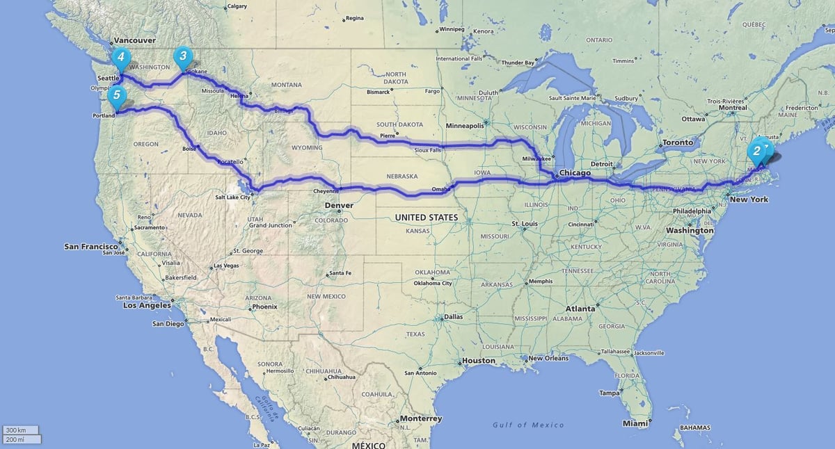
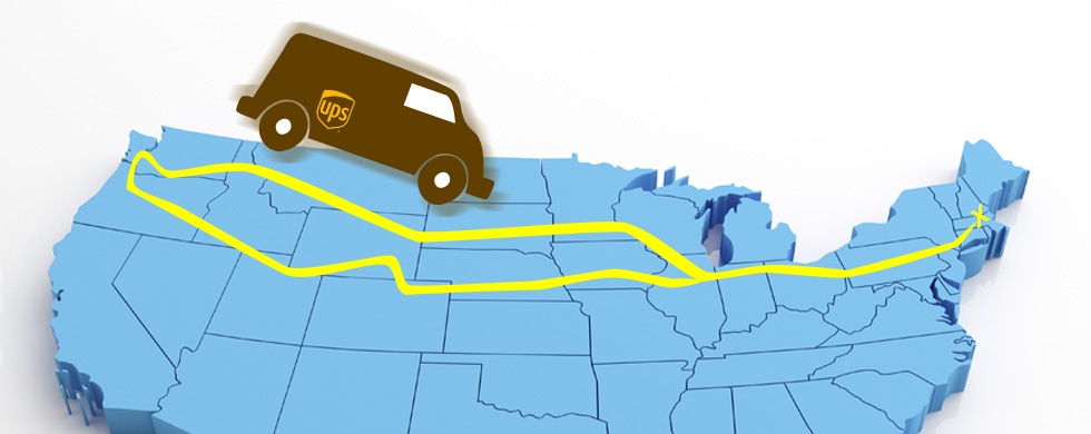
The first shipment and test we did was a UPS ground shipment from our office in Medford MA, out to Seattle, WA and then back. Figure 1 provides a simple map of the shipment route that based upon the UPS tracking information (out, back).

The Equipment
For recording such a long shipment, I had a bit of a problem. I could use one of the shock and impact recorders specifically meant for monitoring shipments, like the ShockLog and ShockTrak from ShockWatch. These use piezoelectric accelerometers with a range ±200g and a sample rate ot 4,096 Hz which are both good. But they only allocate 32 kB of memory per "event," enough for 4,096 data points. I like having millions of data points available to analyze so that I can get detailed frequency information about my environment; those products seem better suited at capturing peak events.
So I turned to the enDAQ products we developed to be good all-purpose tools to make the lives easier for engineers everywhere performing shock and vibration testing. But... it wasn't initially developed with transportation monitoring in mind.
The battery life on these products range from 5 hours at a high sample rate (20,000 Hz per axis) up to over 20 hours when sampling at 100 Hz. That's plenty long enough for many testing application; but not a cross country shipment. Thankfully the enDAQ sensor can record while plugged into an external power source. At first one would assume that any portable USB charger (like those meant for your phone) would work great. Unfortunately most of these portable phone charges have a "smart" auto-shut off feature. They detect when the device it's charging is fully charged, then it shuts off to conserve its battery life. That won't work for this application; we need a charger that can continuously deliver a charge.
It took a little bit of digging to find such a charger; but thankfully a company called Voltaic has an "Always On" mode for two of their charges, the V15 and V44. The V15 has 4,000 mAh battery capacity while the V44 has 12,000 mAh. The enDAQ sensor battery for comparison is only 180 mAh; so these offer significantly more battery life.
I selected an enDAQ sensor (formerly known as a Slam Stick) with a ±500g triaxial piezoelectric accelerometer and a ±16g capacitive MEMS accelerometer with a DC response. I wanted the piezoelectric for the vibration and shock data; but I wanted the MEMS accelerometer also to get a sense of the orientation of the box during shipment and to pick up lower frequency vibration content. There's actually a lot that goes into accelerometer selection, which is why it's nice to have two in one package; get the best of both worlds!
Test Set-up
I configured the unit to record off a 1.5g threshold from the DC MEMS accelerometer channels. Because of the 1g offset for gravity, this is effectively looking for a 0.5g bump. I limited the recording length to 15 minutes, programmed the sample rate of the MEMS accelerometer to 400 Hz and the piezoelectric to 1,000 Hz. And finally I programmed it to be "re-triggerable" meaning once it's finished a 15 minute recording after a trigger event, it will go back to trigger mode.
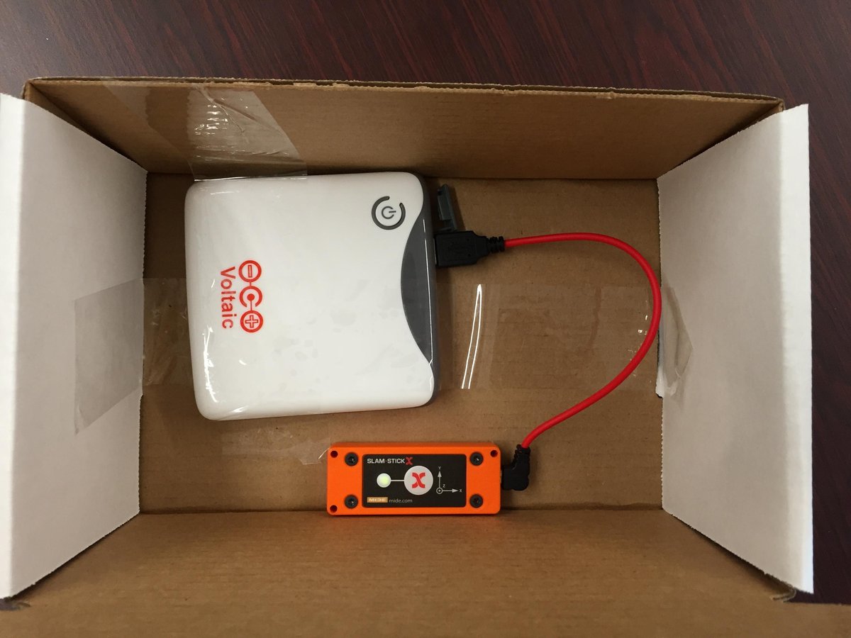
The 500g sensor was mounted to a standard cardboard shipping box with high strength double-sided tape, as shown in Figure 2. A V44 Voltaic portable USB charger was plugged into the unit to extend the battery life. Now we were ready for UPS to pick up the shipment and deliver it to Seattle!

The Results
When I got the unit back I plugged it into my computer and began converting the recordings to MATLAB (check out my post on MATLAB vs Python Vibration Analysis). There were 217 recordings each about 7.3 MB, so 1.5 GB of data overall. I made a quick MATLAB script to loop through all the recording files and folders and pull out some summary information like the peak acceleration level and the axis it occurred in as shown in Figure 3. During transit there are a lot of little bumps of around 1g; but when the UPS folks are handling the box, watch out! They seem to be tossing it around with shock events detected exceeding 100g!
Figure 4 includes a couple other plots from the shipment (click on each to zoom in). By looking at the mean acceleration in each axis of the DC MEMS accelerometer we get a sense of the orientation of the device/box during transit. I had a quick look at the RMS vibration levels of one of the vibration recordings which shows a consistent 0.2g RMS. enDAQ sensors also have a temperature and pressure sensor which samples at 1 Hz; so I was able to plot the temperature and pressure throughout the entire shipment.
GALLERY - Click to enlarge images
Going into the test I wasn't expecting to be particularly interested in either temperature or pressure; I was more focused on vibration. But when I had a look the pressure data I noticed something pretty interesting. It shows the elevation change and corresponding drop in pressure when the truck was driving through the middle of the country! From the UPS tracking information, the box traveled through Spokane on the way out to Seattle; and on the way back it went through Portland. This means that it likely traveled through the more northern portion of the Rocky Mountain range on the way out which is less in elevation as shown in Figure 5.
GALLERY - Click to enlarge images


If we calculate the elevation from the pressure data (see Mide's pressure-altitude calculator for more information - Note: enDAQ is a division of Mide), as shown in Figure 6, you can clearly see the much larger spike in elevation for the second half of the shipment. This matches up nicely with the topographical map of the US and assumed route, pretty cool! For a more in-depth analysis and discussion on this pressure data, check out my quick video blog.
Now let's dive in deeply to look at the vibration data. In Figure 7, I calculated a spectrogram (refer to our overview on vibration analysis for more information on spectrograms) of one of the vibration recordings (the data file is available to download at the end). There is clearly a strong band of frequency content around 3 Hz that remains consistent throughout the recording. This is likely a structural resonance in the truck somewhere. But there were also these bands of intense vibration at 40 Hz and then repeated every 10 Hz. These bands seem to be wavy and could potentially be related to truck speed and tire rotation. Let's find out if they are in this post about calculating speed from the truck's vibration frequency.
Now let's compare the vibration levels to the published mil-standard 810 transportation vibration environment. If we compute the power spectral density (refer to our overview on vibration analysis for more information on PSDs) of that vibration data set it can compared to the published vibration levels for "common carrier (US highway truck vibration exposure)." They don't match up that closely which may be because this is the vibration of a box that is likely not fixed to the truck; it's probably just sitting on a shelf. But for someone who is designing a product that may have some sensitivity to vibration and needs to survive shipping, this data may be very valuable!
UPS Freight Shipment
The Setup
Typically someone interested in measuring the shock and vibration environment of a shipment won't be worried about a little cardboard box in a UPS truck. What an engineer may be worried about though is the environment that a wooden crate strapped to a truck bed sees.
Thankfully, Mide (Note: enDAQ is a division of Mide) was recently shipping a large structure down to Florida for some testing as part of one of our research programs. The lead mechanical engineer for that program was very worried about this structure, a robotic arm, surviving the shipment and wanted to gather some test data to use for future designs. So an enDAQ sensor Slam Stick was our obvious choice!
Unfortunately I can't share any photos of the setup but I can share the data! We set the enDAQ sensor to record at 10 kHz per channel for a ±500g triaxial piezoelectric accelerometer, and set the DC response MEMS accelerometer to record at 400 Hz. The recording length was set at 15 minutes like the ground shipment, and the trigger level was 1.5g. We used a Voltaic portable USB charger again to extend the battery life. And then we scheduled the shipment from Boston down to Florida.
The Results
Because of the high sampling rate this generated a LOT of data over the shipment which lasted just over 2 days. There were 113 recording files, each with a size of 54 MB. That's over 6GB of data, over 3 billion data points. So I used a MATLAB script to churn through this data and plot the maximum shock event detected over the shipment, shown in Figure 9.
The shock levels were much less than the UPS ground shipment but they were more consistently in the ~10g range while the truck was during transit. Now because we were sampling much faster we can have a little more fun with the shock analysis. Specifically, I computed a shock response spectrum on a 1 second period, capturing a couple impact events. I won't dive too deep into pseudo velocity shock spectrum analysis (check out this paper to give an overview); but basically the velocity is what an engineer should be worried about during a shock event, not the peak acceleration level (remember energy is proportional to velocity squared). And the shock response spectrum takes the input shock time history and computes what the resulting pseudo velocity (approximately the relative velocity) of a system would be for a given natural frequency. This let's the engineer determine which frequencies to avoid and understand how different parts of his or her system will respond during a known shock event.
Figure 10 includes a plot of the filtered data (250 Hz low-pass Bessel, and a 2 Hz high-pass Butterworth) alongside the pseudo velocity shock response spectrum. That "four coordinate" plot can be a lot to take in initially. Because of the relationship between acceleration, velocity, and displacement, all this information can be displayed one plot relative to natural frequency. The filtered data is available to download in a CSV (Excel readable) file.
GALLERY - Click to enlarge images
The shock data is cool to look at; but what story does the vibration data tell? First, let's compare a PSD of one of the vibration recordings to the mil-standard 810 transportation vibration environment, shown in Figure 11. The shape of these match up quite well! The major difference between the two is the amplitude which could be explained by the damping that the wooden crate provided.
From the mil-standard, they state "if it is known that significant excitation is expected below 10 Hz, extend the curve and shape it to comply with the available data." As always with vibration and shock testing, it's best to go out and gather the relevant data that you need for your environment. You can't rely on the standards to give you everything, they just provide a good background and foundation. If an engineer designed a system with a known resonance of around 4Hz and relied only on the mil-standard data, he/she may assume that the system will be able to survive the shipment without issues. But in actuality the vibration environment may in fact be exciting that resonance and potentially damage the system.
Lastly, let's take a look at a spectrogram from one of the freight shipment recordings, shown in Figure 12. The enDAQ sensor was much more directly coupled to the truck bed in this shipment (mounted to a wooden crate strapped down) versus the ground shipment when it was inside a cardboard box which was probably loosely placed in the truck. Therefore the spectrogram tells a much more interesting story! I believe you can very clearly see the vibration environment change with time and in such a manner that suggests its related to the truck's speed (tire rotation).
Conclusion
Going into this analysis, I was hoping to gain an insight on what happens to our shipments during transit. We learned that standard packages shipped via UPS ground are relatively aggressively handled, seeing impacts of over 100 times the acceleration of gravity! Even freight shipments see some large impacts while on the road of over 20g. If that's all you are interested in, the peak shock levels, then a standard transportation shock recorder, like the ShockLog and ShockTrak from ShockWatch, may be all you need. But if you want more...
I really enjoyed diving deeply into the vibration environment and computing shock response spectrums off some of the events. This is the type of analysis that can only be done when you have the real raw data, and data sampled at a relatively fast rate (>1 kHz). We found a correlation in the vibration data to truck speed, we found resonances in our environment that may affect an engineer's future design, and we had some fun!
I encourage you to download the data (click here for download page) and do your own analysis. If you'd like to learn a little more about some of the analysis I ran through in this post, download our free Shock & Vibration Testing Overview eBook. In there are some examples, background, and a ton of links to where you can learn more. And as always, don't hesitate to reach out to us if you have any questions!
For more on this topic, visit our dedicated Shipping and Transportation Monitoring resource page. There you’ll find more blog posts, case studies, webinars, software, and products focused on your shipping and transport monitoring needs.

